An extra small concern may be the high burden voltage in some DMMs (the voltage drop in their "shunt" current measuring resistor) for their mA range. You can test that by measuring the red mA range terminal with a DMMs red probe when set for Ohm. Don't be surprised if finding 10 Ohm+. Combine all that and you may need VDD+ to really measure at 10V across the JFET in current mode test. One of the reasons the FETS bias somewhat harder than expected when put in PCB. Can be a problem or not depending on the circuitry concept and the JFET type curve. Some don't change much their IDSS over 2V, other types may do. It can be enough of a concern if measuring IDSS at low VDD for near 2*Pinch off VDS use for instance.
Tanks Joachim and Salas
18V and 1 K sound fine besides Paradise runs at 18 V so even better
PS
I have a Little test rig for HFE tanks to Hesener for help on that one
The circuit I have posted came out of Salas Simplistic tread
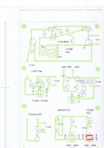
I am drowing a PCB to include those 2 test circuits + Led Voltage tester and VBE tester
Again Led voltage is out of Simplistic and VBE test is one I have posted a while ago (apolologies due as can't recall source for that)
VBE test is included as I got space on 160 X100 euro card.
I hope this may be useful for Music loving population which may not have test gear avvaliable.
I got a first PCB in the bath at the moment and as soon as tested I will take this forward
18V and 1 K sound fine besides Paradise runs at 18 V so even better
PS
I have a Little test rig for HFE tanks to Hesener for help on that one
The circuit I have posted came out of Salas Simplistic tread
I am drowing a PCB to include those 2 test circuits + Led Voltage tester and VBE tester
Again Led voltage is out of Simplistic and VBE test is one I have posted a while ago (apolologies due as can't recall source for that)
VBE test is included as I got space on 160 X100 euro card.
I hope this may be useful for Music loving population which may not have test gear avvaliable.
I got a first PCB in the bath at the moment and as soon as tested I will take this forward
Before i used a curve tracer i measured with 18V and a 1kOhm resistor.
Is New Atlas PRO now capable of differentiate therminals on J FETS ?
Old one could not ....
Nope. You can measure it.
Make a simple preamp. Say a common source single ended BOZ with a gain of ten.
Measure frequency response one way and the other way around. One conection may be more extended in the treble.
That is the correct one. That is beacuse capacitance in one direction is a bit lower but not much. I even found J-Fets that where totally symmetric.
Tank you Joachim
And apolologies for temporary Hi Jack of this tread
Here is Pre view of test all rig
Can pick 4 different voltages on the LM 317 regulators
Dill switches and IC sockets for now
Finished one will have rotary switch for selecting test feature and meter connections.
And apolologies for temporary Hi Jack of this tread
Here is Pre view of test all rig
Can pick 4 different voltages on the LM 317 regulators
Dill switches and IC sockets for now
Finished one will have rotary switch for selecting test feature and meter connections.
Attachments
There are some news on the Paradise front.
I talked to Hesenr today. He made some simulation what the big elcaps do at the input.
We already talked about that they have to setle down a bit to "form" so that the leackage current goes down. That has a direct effect on the output offset that gets a bit down with time. Ones they have settled and the real values and types are known he found a slight resonance peak at ca.80kHz that can be damped with a snubber. He is working on the values and we will inform you when that has proven to work.
It has to be seen if that improves the sound. We also talked about a new group buy of PCBs. There are some new and late commers and the issue is also discussed on the German Analog Forum. I also have an idea for a balanced Paradise that uses two PCBs per side for a total of four. A bit over the top but again there is some interest to explore that option.
Almost got spontaneous brain burn out caused by math symbols and 2 remaining brain cells being almost 50 proof.
Nothing to worry about.
In fact gm = 2 x (Idss / Vp) x ( 1 - Vgs / Vp)
But as ( 1 - Vgs / Vp)2 = Id / Idss
gm = ¦ 2 x (Idss / Vp) x sqrt(Id / Idss) ¦
So at Vgs =0 you have gm0 = ¦ 2 x Idss / Vp ¦
It is all the same.
We already talked about that they have to setle down a bit to "form" so that the leackage current goes down. That has a direct effect on the output offset that gets a bit down with time. Ones they have settled and the real values and types are known he found a slight resonance peak at ca.80kHz that can be damped with a snubber. He is working on the values and we will inform you when that has proven to work.
I will wait for that option before I continue populating my new boards
")
Today my IRC RC55-D's are at the end of their life, now I need to find me a new most favorite resistor. (66-RC55-D Metal Film Resistors - Through Hole | Mouser ).
).Yes they are, but 100ppm is not for me (25ppm at the most).
the specs look good.
Yes, but the RC55-LF-D is two or more times as expensive than the (now obsolete) RD55-D. 66-rc55lf-d Metal Film Resistors - Through Hole | Mouser
I have been using those for a while
Buy Through Hole Fixed Resistors RC55Y precision resistor, 10k2 0.25W Welwyn RC55Y-10K2BI online from RS for next day delivery.
IMO a bit less harsh than IRC but magnetic wires
Buy Through Hole Fixed Resistors RC55Y precision resistor, 10k2 0.25W Welwyn RC55Y-10K2BI online from RS for next day delivery.
IMO a bit less harsh than IRC but magnetic wires
When they are more expensive there must be a reason.
In this case is that RS is realy expensive but browser is easier to folow so one may need to do same virtual leg work...