Here about noise in J-Fets :http://www.diyaudio.com/forums/pass-labs/175040-more-fet-noise-measurements-euvl.html
When either I or FwD or whoever else volunteers such as sample have a safe model up and running (maybe it would be better having a couple of people checking since results seem to vary by changing simulator) we could try all these different solutions to try to lower noise and improve DC.
At now, I am still not 100% sure that the circuit could work properly and we should also definitely at least try to correct for thermal drift if possible.
I would also like to check if this is an inverting circuit or not as it could be another potential problem.
All in all, the project sounds very promising to me.
Last edited:
when either I or FwD have a model up and running we could try all these different solutions.
I am still not 100% sure that the circuit could work properly and we should also definitely at least try to correct for thermal drift if possible.
I would also like to check if this is an inverting circuit or not as it could be another potential problem.
All in all, the project sounds very promising to me.
Stefano, do not expect such a solution from me, it is not my 'thing'/expertise to do so and I will not have the time (in any near future) to learn that skill. The reason that I did this was just as a silly-time-to-consume exercise and I wanted to get some insight how an input stage like this operates. More like solving an interesting puzzle. There is a contradiction (somewhere in there) as I did it and I cannot, but that is how I function
")
In all things that I ever designed and or build there where never any fet’s (of any kind (other than for simple current sources with jfet's)), that needs to change and that is why I took the puzzle (there is no game in looking at stuff that works
). Oh yes I did an amplifier using the ‘Lazy Cat’ BIGT’s, and yes there are a few hexfets (I love those) in the PSU, and finally (even before commercial hexfet’s existed) I did a 100W amplifier using hexfet’s (mmm… that’s more than 20 years ago) (yet again some contradicting information ).For sure, both ccs and cascoding bjt parasitics should be as low as possible. Maybe I should elaborate more about schematic in post #7843. I'm sure JG knows this stuff, but in essence gyrator is a ccs with "natural" servo that keeps stable DC operating point. It's plain simple, divider R6/R8 senses output voltage and adjusts Q13 gate voltage increasing/decreasing current. C2 sets corner frq. ("authority of servo"). I have been using this gyrator with IRF9610's in my preamp for loading ECC88 for a very long time now, and it sounds superb. Some experimenting might be needed for finding practical values of R6/R8 and C2, but this should work with IRF9610 here too, just more thd.One other thing :
Sampler mentioned that distortion goes down and bandwidth goes up when the output capacitance of the CSS is low. I though that this can be ameliorated by putting a resistor in series with the CSS like 1kOhm. It worked in my Tube RIAA.
I don't want to repeat my self, but I posted a link in #7824 to a thread, were similar circuit was discussed and nit picket to smallest details, I recommend it once more for everybody fighting with basic concept in LTspice. There is great input from Scott, JC, Syn09 and others... JG too !
Although I don't agree with verdict that whole concept of two ccs's fighting with each other which one sinks or sources more current is flowed in essence, but it doesn't make life easer for sure. I will make proto tomorow, now I'am obligated to go and watch new episode of Walking Dead For sure, both ccs and cascoding bjt parasitics should be as low as possible. Maybe I should elaborate more about schematic in post #7843. I'm sure JG knows this stuff, but in essence gyrator is a ccs with "natural" servo that keeps stable DC operating point. It's plain simple, divider R6/R8 senses output voltage and adjusts Q13 gate voltage increasing/decreasing current. C2 sets corner frq. ("authority of servo"). I have been using this gyrator with IRF9610's in my preamp for loading ECC88 for a very long time now, and it sounds superb. Some experimenting might be needed for finding practical values of R6/R8 and C2, but this should work with IRF9610 here too, just more thd.
I don't want to repeat my self, but I posted a link in #7824 to a thread, were similar circuit was discussed and nit picket to smallest details, I recommend it once more for everybody fighting with basic concept in LTspice. There is great input from Scott, JC, Syn09 and others... JG too !
Interesting.
Would you mind elaborate the circuit with IRF9610? Apparetly circuit doesn't seem to operate in my simulator.
Also, if you don't mind where did you get the model for the gyrator?
I have never used this device before.
When you use the IRF instead of the Zetex the major difference will boil down to the Ugs where you get the same current, output capacitance not considered which is higher in the IRF parts. Look at the curve of Ugs against idle. One problem with steep mosfets is that tiny changes in Ugs make big changes in idle.
Replace ZVP4525 with IRF9610 or any other Pmos with reasonably low Coss and bias it properly for required current.Interesting.
Would you mind elaborate the circuit with IRF9610?
Sorry to hear that.Apparetly circuit doesn't seem to operate in my simulator.
Not sure what you mean, but ZVP4525 spice model can be found here.Also, if you don't mind where did you get the model for the gyrator?
I have never used this device before.
Well, it is more like doubled, anyway.
yes I see your point.
I was looking at one of the link you posted before and made me want to use the IF3601 for this
The dual package monolithic will achieve an extremely low noise and thermally coupled if CCS is stable should lead to a simple but extreely low noise and thermally stable design.
What do you think?
Anyway like I said I would like to have the model up on my simulator to be able to make modifications for everybody.
Otherwise sampler could be doing that work if he feels like, I don't mind doing it if he is busy.
Still I would like an explanation as to why his model works
is it because of the current set on the CCS?EDIT: Thanks Sampler for the extra info, I will try to see if I can work this issue out.
The IF3901 is like a pink elephant or a unicorn if you wish.
Can not wait until you get some Stefano.
The CSS has to provide THE EXACT SAME CURRENT THEN THE INPUT STAGE PROVIDES AT IDDLE, ALL THE TIME. If that does not happen the DC voltage at the output node is not EXACTLY at 1/2 voltage of the supply. That condition gives the MAXIMUM DYNAMIC RANGE ( Tietze- Schenk ).
Last edited:
High Way the Hard Way :Tietze-Schenk Homepage
There is an english edition.
There is an english edition.
It is wise to use P-Channel Mosfets, Sampler. They are much less noisy then the N-Cannel variety.
You can find that here :Analog Design Essentials, Sansen
You can find that here :Analog Design Essentials, Sansen
Attachments
Question :
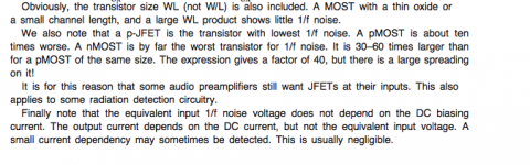
What kind of P-Channel Mosfet has the least noise provided that you run it on 10 times the idle then a comparable BJT ?
You can win one bottle of Los Royales Reserva 2007.
I really do not know, but if I was guessing I would go like this, the larger the mosfet the better
in actual fact a large (hexfet) mosfet is a matrix of paralleled fets and thus the more in parallel the better. Thus I think the larger the dye the better. Just my guestimate! You know where to send that bottle