The paradise has a special riaa filter without components in series with the signal.Why not bring it here..???
I am not completely sure my findings are correct although my math simulation gave results very near those simulated by stefano.
I am used to work with Salas that already proved to be able to withstand my strangest questions.

Must do my homework and be sure before I post the fundaments of my calculations.
I have been wondering myself for a while the following thing:
On the front gain stage if 2SK170 and 2SJ74 are used, isn't it desirable to have GR grade at lower current and having a lower source resistance thus low heat dissipation other than using a BL or even worse a V grade and pump a lot of current current thus increasing heat dissipation or using a higher source resistance to degenerate loose gain and increase noise?
In other words why would a V grade be so desirable?
I know that these jfet don't have a zero tempco other than running I believe a V grade full current but then this bias point is not idel soundwise, so why would bother with higher current here?
ok, but if you want to keep the same current value for dissipation reason, let's say for the sake of the discussion 3mA, with the BL or V grade you will have to increase the degeneration resistor thus increasing noise on a MC stage, am I missing something?
Or, on a No-Global-Feedback design you have to loose some of the OL gain thus degenerating, thus adding noise.
Am I still saying something non-sense?
Or, on a No-Global-Feedback design you have to loose some of the OL gain thus degenerating, thus adding noise.
Am I still saying something non-sense?
Are you talking now about thermal equilibrium or lowest distortion ?
Problem with J-Fets is that they do not react that good on degeneration then bipolars do.
The distortion profile even gets more complex. I have published here several times research by Boyk that shows that fact very educative.
I hope i can find it again.
Problem with J-Fets is that they do not react that good on degeneration then bipolars do.
The distortion profile even gets more complex. I have published here several times research by Boyk that shows that fact very educative.
I hope i can find it again.
Thank you for the quote, I ha never read that before.
I was more concerned about thermal equilibrium though but this document hits the spot anyway
.I can't find any detailed information on thermal stability for the K170/J74 and in my current design 3 stages the thermal drifting is really remarkable (in a bad sense it wonders like +/-100mV or more) and I don't know how to fix it other than helping it a little bit by using some thermal tracking techniques i.e. heatsinks or thermal grease and tie zip.
Audio Research packs the J-Fets in a common plastic container.
I run the 2SK170 and 2SJ74 near Idss where is a sweet spot in drift and we need as much Gm anyway for low noise and high gain.
There is another sweet spot with lower current that was discussed on another thread somewhere but i forgot what it was.
I run the 2SK170 and 2SJ74 near Idss where is a sweet spot in drift and we need as much Gm anyway for low noise and high gain.
There is another sweet spot with lower current that was discussed on another thread somewhere but i forgot what it was.
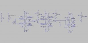
This is the concept schematic. I do create a sub regulation at each cascode with low Z discrete shunt regulators and it is battery powered followd by 2/3 descrete "high current" shunt regulators.
My last protoitype only had 2 gain stage different feedback configuration and only one passive RIAA network.
I nevertheless deicided to increase to 3 lower gain on each stage and split the RIAA in 2 to have maximum accuracy, no custom values, and higher headroom.
Unfortunately I haven't listened to this one yet because I can't build a Servo that works around and noise at the output is not wideband for unknown reasons.
Thermal drifting is pretty bad and everything has to be enclosed and thermal tracked.
I was unable to find any sweet spot in order to maximize thermal.
If you want to take this off line I can send you some scope shot of the output.
My email is:
stefano_rumori@yahoo.it
P.S. how do you determine your sweet spot on the K170/J74?
Attachments
This looks MASSIVE.
I'll stay tonight on the balcony, looking west.
Maybe i'll see the light.
No lights yet, here a small status (stupidity) report,
Last saterday the board was compleated, sunday during the day it was mounted, and sunday evening I destroyed it
After first power up I could not set idle current, so I took the meter and the nearest probing pin (it was a (to) large one), and started metering some points. The next thing is, I shorted 70 Volts against the Vas-cascode, this destroyed the cascode and put lots of volts on the opamps... you can guess it from there.
Next weekend there will be time, and the fight goes on ... will be continued ...
Short update, the Paradise group buy is sitting at 194 sets (388 boards) now !! This is massive.... With the quality of CDs making vinyl "unnecessary", who would have thought that.... ;-))))
We will be closing the group buy on monday August 13. Fortunately, a few people have stepped up and will be helping me doing all of this, many thanks in advance you know who you are! We may even have another group buy for the components, let's see
We will be closing the group buy on monday August 13. Fortunately, a few people have stepped up and will be helping me doing all of this, many thanks in advance you know who you are! We may even have another group buy for the components, let's see
Yeah, why don't we start that now too? What do you think?
With this massive participation cost will go significantly down...That way everybody can get boards and parts at the same time.
Sounds like a good idea?
I am quite happy with IRC resistors tanks Fdw.
What I would raly like is super duper capacitors especialy on RIAA so count me in
I am alright for the BC altrougt I will need to work out beter matching for the 2000 I have.
PS Mouser sell those BC xxx40 at £9 for few undreds so no problem there
Just two questions..... What should be the best Idss for the J310 in the output buffer ?
I am planning to use 2mA Leds on the shunts... is this a good idea ?
Hey guys... the LED question is the most important one (already bought those)... as for the jfets... is there a prefered Idss value... I do not mean anybody must match the fets, because I know it will work, but as I must measure all the parts before i stuff them (must be sure everything is ok at startup this time), I can choose Idss.
The J310 helper Fets have quite high Idss. Chose the ones with the highest Idss if you will. The 2SK170 and the 220 Ohm resistors degenerate them much so matching is not that critical. What you will experience is that a voltage develops over Drain and Source of the 2SK170. That can stray, even when you select the helpers for Idss. Ideally you should select them for Ugs too so that the Drain-Source voltage over the 2SK170 is the same in both channels.
Last edited:
The J310 helper Fets have quite high Idss. Chose the ones with the highest Idss if you will. The 2SK170 and the 220 Ohm resistors degenerate them much so matching is not that critical. What you will experience is that a voltage develops over Drain and Source of the 2SK170. That can stray, even when you select the helpers for Idss. Ideally you should select them for Ugs too so that the Drain-Source voltage over the 2SK170 is the same in both channels.
A tip on how to select them for Vgs..... ?
No news = good news so the LEDs ar ok I presume