Good, that you like the modification. I found it sounded also more dynamic but every system is different. Could you do me a favor and rewire the mirrors too to the new circuit ? I can do that too but i thought when you are at it anyway it would safe some time, of cause mine !
What modification are you refering to ?
PS: I also like your 3D p2p builds.
While waiting for my hesener "doctored" boards, I am preparing a suitable raw DC psu... what is the current running in the paradise shunts ?
I mean, what is the paradise current consumption while idling ?
I found it:
The boards are 120 x 210.3 mm each.
The regulator needs Max(out) + 6Volts on the input side
Paradise should draw 150mA each rail
Am I right ?
sorry for my late reply, yes all these values are correct. i am surprised you haben't received the boards yet, guess there are delays due to the public holiday
I just have a funny idea:
You should open up a hospital : Prof.Dr.A.Hesener "Magic Treatment of High End Audio Prototypes that went into Stasis or Wild Oszillation".
haha... that would too nerve-wrecking to do over longer time... i must admit though that i did work as a service technicican for a shop selling musical instruments for a while, and i learned a lot. searching for a mistake in something you know has worked before can be challenging, frustrating, ...... but ultimately it has to work again so giving up is not an option.....
but it is so satisfying when it works, finally ;-)
I found it:
The boards are 120 x 210.3 mm each.
The regulator needs Max(out) + 6Volts on the input side
Paradise should draw 150mA each rail
Am I right ?
Sorry to see this a little late. The PSU runs at 160 mA, so you need 2 x 160 mA = 320 mA minimal. You need 34 Volts on the regulator input (or a bit more, up to 40 Volts will be o.k.). The power disipation will be 34 - 24 * 320 = 3.2 Watt minimal ans 40 - 24 * 320 = 5.2 Watt maximall. More information can be found in message 5650 http://www.diyaudio.com/forums/analogue-source/154210-mpp-283.html#post2970304.
Regards,
Frans.
sorry for my late reply, yes all these values are correct. i am surprised you haben't received the boards yet, guess there are delays due to the public holiday
Alfred, The 6 Volt's is the minimum value, for absolute top performance I would like to see a bit more (10 Volt's would be nice). P.s. I am a bit late also
I worked as a repairman too. That was in the 80th in the High Tech industry.
We made power supplies for Sputtering up to 90kW. That was not only frustrating, partly because there was no complete documentation ( specs could change in a minute and Engineers left by the week ), but it was also dangerous because i had to short circuit them to test them for safety. That was with a 2m long Bakelite "Arm". The sparks i made that way could be a meter long.
We made power supplies for Sputtering up to 90kW. That was not only frustrating, partly because there was no complete documentation ( specs could change in a minute and Engineers left by the week ), but it was also dangerous because i had to short circuit them to test them for safety. That was with a 2m long Bakelite "Arm". The sparks i made that way could be a meter long.
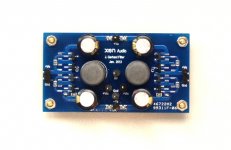
Maybe that does not belong here but i designed an analog filter-buffer that comes behind the new compact DA converters from ESS and Burr-Brown that have inbuilt Opamps and can be used without anti aliasing filters. My filter-buffer is based on coils so it is inductive. I thought that putting a filter in series is better then shunting the potential junk over 20kHz to ground. It is of the aperiodic type so it is a bit softer then Bessel to have a good time domain behavior. The buffer is the same then in the new Paradise but build in SMD by Euvl and his team. I am looking forward to test it in my system.
Attachments
Sorry to see this a little late. The PSU runs at 160 mA, so you need 2 x 160 mA = 320 mA minimal. You need 34 Volts on the regulator input (or a bit more, up to 40 Volts will be o.k.). The power disipation will be 34 - 24 * 320 = 3.2 Watt minimal ans 40 - 24 * 320 = 5.2 Watt maximall. More information can be found in message 5650 http://www.diyaudio.com/forums/analogue-source/154210-mpp-283.html#post2970304.
Regards,
Frans.
Update: The numbers above for power consumption are the minimal's the maximum's are (when the RIAA is disconnected) 34 * 320 = 10.88 Watt or 40 * 320 = 12.8 Watt.
Regards,
Frans.
Last warning to ATL lab from Brussels :
Reduce your power drain for your whole High End Audio chain to under 20W !

We will debate this, and ask for 20W per qubic CM ... or else ...
Send in the Cubes !!!!!
Here is Holgers Plan :hb unplugged | Holger Barske
Here is Holgers Plan :hb unplugged | Holger Barske
