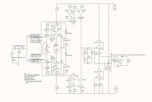
Together with Joachim I have drawn a revision 2 paradise...I have taken away the fuzzy buffer and fitted the simple cascoded Jfet buffer.. I have also changed the insertion point of the servo where it simply adjusts the center voltage between two very high impedance current sources. (<<30Mohm)
for the mirror transistors I suggest to use arrays(here 3904/3906). This will simplify the build and greatly reduce the risk of errors. Also the need for hfe matching is not present as the high impedance related to structure an will be present regardless of hfe. (33 or 85 Mohms are both a lot of ohms)
For the PCB layout I think it would be goo to place the housekeeping and servo to the far left, input in the middle and output to the right.
Attachments
Thanks Michael, that looks very good. Now Hesener has to add Frans´s new PSU and make a new layout. I hope this version will play without trouble.
First of all I need to re-calculate, and specify, the PSU for 18 Volt output (I see) (correct me if I am wrong
") ). Not much of a change though, but has to be done.
). Not much of a change though, but has to be done.Holger, the first Paradise stands as it is. When i can remove the ozcillation at 40MHz i can recommend that version for DIY too for the ones that are a bit more experienced.
We simply ran into too much trouble to further develop that version.
Actually it sounds very good and is quiet.
The new version is simplyfied without loss of performance, quite the contrary.
The Mirror is higher impedance and less distortion. It runs on 18V now ( Frans you are right ) because then the servo opamp does not need extra attention for PSU.
There is a surprising amout of N-channel Fets that work in the buffer. Some of them really inexpensive so it has not to be the somewhat expensive 2SK170.
The old Paradise buffer is simply too fast and complex for DIY, this is RF stuff. We can use BCs in the mirror. That is not a problem. Matching is less critical in the new design. MIIB simply wanted to make it fool prove and i think that is a good idea. Not every body has to understand all the details to make a successfull build. I think that is important, to make it as easy as possible.
Last edited:
Somewhat unfortunate. I really liked the idea of all signal handling done by BC transistors.
Yehhh, I'm go'na miss t'e litt'le b'stard's
it wa's a real par'ty go'in on.
Compared to the "old" paradise.. I do believe this revision 2 is way better...
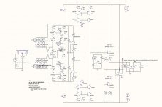
Feel free to use the BC transistors in the mirror also. I think that they are a brilliant choice, but as stated, the quad arrays makes the design less prone to errors.
I have been working a little more and I can see one Jfet is at the limit, so it has now in doubled and current set at app 16mA input/mirror and 10mA through the buffer (only one sk170 left due to lowish cob. bf862 would also make a fine choice here..)
total consumption is then app 75 mA at both rails. Current can be lowered to app 50 mA if current is set at app 10ma trough the input/mirrors.(a change from 4 to 2,5mA each input transistor)
Attachments
Last edited:
Compared to the "old" paradise.. I do believe this revision 2 is way better...
Feel free to use the BC transistors in the mirror also. I think that they are a brilliant choice, but as stated, the quad arrays makes the design less prone to errors.
I have been working a little more and I can see one Jfet is at the limit, so it has now in doubled and current set at app 16mA input/mirror and 10mA through the buffer (only one sk170 left due to lowish cob. bf862 would also make a fine choice here..)
total consumption is then app 75 mA at both rails. Current can be lowered to app 50 mA if current is set at app 10ma trough the input/mirrors.(a change from 4 to 2,5mA each input transistor)
I will setup the PSU with an 75 * 1.5 = 110 mA CCS.
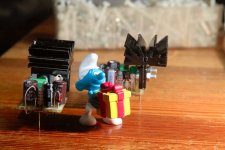
Here is one, the mini ATL PSU + side. About 5 cm2
And now there are two (+15V and the 'dark'-side -15V)
Attachments
so you plan to integrate those into the center of the paradise too..??
No these are intended for amplifiers, when you need to feed one or two opamps, they are underpowered for the 'Paradise DIY'. See also http://www.diyaudio.com/forums/analogue-source/154210-mpp-285.html#post2976508 but they operate exactly the same.
Really cute. We should do a PCB for this mini shunts too. Any voluntary ?
I am working on that