Frans, i like the ones with the switched coils. Do you need a microprocessor to steer this ?
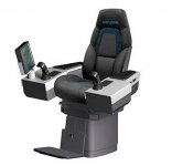
The ATL people showed me the steering setup (I did manage to make a picture of this top secret installation), keep it private please.
Attachments

Good advice.
Then the question is; Did the ATL make a good design (according to these standards)
") It is a bit asking for a compliment, but we (the ATL people) cannot make the judgment myself
It is a bit asking for a compliment, but we (the ATL people) cannot make the judgment myself Regards,
Pleasing ATL,
Frans.
Rams would take the most simple that does the job just right. Then he would design a compact, un obtrusive cabinet that does not go out of fashion and makes the function self explanatory. Simple they look all at the surface........
But what is the job ?
Improve the sound ? Measure better ? More economical them more expensive solutions that do the same thing ? Innovative ? Does it do something that has not being done before ? Do people need that to express themselves better ? Is it so important that i can not be without it ?
But what is the job ?
Improve the sound ? Measure better ? More economical them more expensive solutions that do the same thing ? Innovative ? Does it do something that has not being done before ? Do people need that to express themselves better ? Is it so important that i can not be without it ?
Rams would take the most simple that does the job just right. Then he would design a compact, un obtrusive cabinet that does not go out of fashion and makes the function self explanatory. Simple they look all at the surface........
But what is the job ?
Improve the sound ? Measure better ? More economical them more expensive solutions that do the same thing ? Innovative ? Does it do something that has not being done before ? Do people need that to express themselves better ? Is it so important that i can not be without it ?
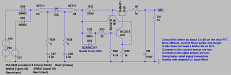
The nice thing about the 'Area 51' circuit is; the schema with the lowest component count (switches and filter not counted) is actually the best (simulated measurements by ATL). That is what I like about it!
Ok, now we have a clue that can even being done by children. Pick the circuit with the least component count. Bingo.... that is the holy grail.
Maybe I hear some sarcasm in there? But I cleared (by the people of ATL) to help you identify the current 'best' circuit, it’s the attached one (circuit M in the file).
Attachments
I would like a dual sided board, when home brew (single sided) you would do the bottom layer only and have one or two jumpers; otherwise they would go on the top side. Having two sides you would use the topside as a ground plane. How would that be?
The MKP's would be fine with me, but my say on capacitors should not be definite
Back from Saturday shopping
New Coldplay CD on the spinner.
I have increased the track size to 2mm
Still using the 5 mm foot print for 100nF Caps
I have added the top layer Ground plane
(This can be tied up to proper ground on any of the pins
For clarity I have removed the bottom layer cooper poor area
And added a few pads for the output capacitors
The only concern I have is the length of the (highlighted) darker track.
Edit time was about a couple of minutes if that so no problems in any changes
On the caps the 5 mm size may be a limit to what is available
If this was 22.5 there are 4 or 5 types of MKP caps available from the like of
Farnell.
Is not trouble at all to make any changes as I said before it is an honour to be here.
PS I could not use color as PDF size is 160Kb If you need any DXF Gerbers or such I will email
Attachments
Back from Saturday shopping
New Coldplay CD on the spinner.
I have increased the track size to 2mm
Still using the 5 mm foot print for 100nF Caps
I have added the top layer Ground plane
(This can be tied up to proper ground on any of the pins
For clarity I have removed the bottom layer cooper poor area
And added a few pads for the output capacitors
The only concern I have is the length of the (highlighted) darker track.
Edit time was about a couple of minutes if that so no problems in any changes
On the caps the 5 mm size may be a limit to what is available
If this was 22.5 there are 4 or 5 types of MKP caps available from the like of
Farnell.
Is not trouble at all to make any changes as I said before it is an honour to be here.
PS I could not use color as PDF size is 160Kb If you need any DXF Gerbers or such I will email
Yes that is cool, all high frequency artifacts immediately shunted to the ground plane
I am gone order lots of them I like the layout better and better too. And all done by hand. For me it can be the bigger sized caps. You get them in PP quality.
No Frans, i had a gut feeling that it should be simple. I have nothing against children, quite the contrary, they have a lot of that we have lost and they are honest.
MiiB, i am running out of well matched transistors. The ones from Frans where very good but the ones from Reichelt did not match at all. I have now ordered some from Fairchild.
They invented the modern planar epitaxial transistor so i hope they have some pride left.