Yea cool idea to but not now I think
just commenting on the use of X1 caps.
Here is my second take on Paradise Preregulator
It needs the TO 220 for the diodes and proper autline for caps of your choice.
Tracks are bit longher than before and I think it may be beter to change again
just commenting on the use of X1 caps.
Here is my second take on Paradise Preregulator
It needs the TO 220 for the diodes and proper autline for caps of your choice.
Tracks are bit longher than before and I think it may be beter to change again
Attachments
before engaging the servo...I would rough trim the offset by adjusting the current set in either the upper or the lower current mirror, not so much to avoid offset at output, but to ensure that the servo dosen't have to unbalance the currents in the gain-transistors too much
Hi Mibb
I am still collecting parts but this is very important... What is the current mirror you are refering to ?
How can I adjust it´s current ?
PS: I will start populating tonight
")
I think Michael suggests that you first build the paradise without connecting the servo.
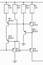
A certain DC offset will apear over the RIAA. You can then trim the offset down by adjusting one of the 120 Ohm resistors in the upper or lower current mirror. When you reach a minimum you can then connect the servo so it has less to do.
A certain DC offset will apear over the RIAA. You can then trim the offset down by adjusting one of the 120 Ohm resistors in the upper or lower current mirror. When you reach a minimum you can then connect the servo so it has less to do.
One reminder, also scan the rails with oscilloscope thoroughly when all will be running. Since the shunts are a dead ringer for initial V1 and ''Q6 mod'' topology I am confident they are difficult to oscillate in a practical build, but with non gate stopped ''fast'' 9610/610, with C104/5 smack on error amp's base, and small terminal cap plus chip based CCS there is enough differentiation to need make sure about confirming in any new layout.
I think Michael suggests that you first build the paradise without connecting the servo.
A certain DC offset will apear over the RIAA. You can then trim the offset down by adjusting one of the 120 Ohm resistors in the upper or lower current mirror. When you reach a minimum you can then connect the servo so it has less to do.
Sorry to budge in, but I would not do that. Changing Re (in one leg of a current mirror) will change the gain and that may be bad also, use the servo to solve this and you will have equal gain in both legs of the mirror.
Some simulations should be done to see what the best practice, one of the next 3 should do:
1: Leave the difference and then let the servo solve the problem.
2: Adjust the resistor to resolve the current difference (the servo will fix dynamic behavior).
3: Adjust the resistor to remove half the difference (and maybe get best of both (1 and 2
).Regards,
Frans.
Last edited:
One reminder, also scan the rails with oscilloscope thoroughly when all will be running. Since the shunts are a dead ringer for initial V1 and ''Q6 mod'' topology I am confident they are difficult to oscillate in a practical build, but with non gate stopped ''fast'' 9610/610, with C104/5 smack on error amp's base, and small terminal cap plus chip based CCS there is enough differentiation to need make sure about confirming in any new layout.
I do have some second thoughts on that maybe we need to add a little gate stopper in there (we can always use a wire bridge on the PCB). None of the currently build versions report oscillating (but there are 2 only (that I know of)).
Regards,
Frans.
this is the only chritical piont as i see it....reason is that even small differences in the mirror resistors will cause the the riaa circuit offset values to slide up and down, as a product of the mirror output impedance (which is big) and of the combined DC impedance of the RIAA network and buffer impedance. even 1 ohm makes a big differnence...So this for sure needs some trimming. 10K trimmer i both positions would not be bad....
The buffer has a permanent -15 mV offset (in my simulations) which is corrected by the servo, So it could be a good idea to adjust the RIAA node to app +15 mV or simply 0 mV after the buffer
The buffer has a permanent -15 mV offset (in my simulations) which is corrected by the servo, So it could be a good idea to adjust the RIAA node to app +15 mV or simply 0 mV after the buffer
Frans:
I am confident from LT SPICE analysis that your enhanced work is well analyzed for PM, but its good to look on testing basics first when firing up any new PCBs for compatibility of layout and load in everybody's build. Just good practice before looking to any other things that may dither and could be routed elsewhere. But I have reasons to believe it will go 100% taken the meticulous preparations you guys did.
I am confident from LT SPICE analysis that your enhanced work is well analyzed for PM, but its good to look on testing basics first when firing up any new PCBs for compatibility of layout and load in everybody's build. Just good practice before looking to any other things that may dither and could be routed elsewhere. But I have reasons to believe it will go 100% taken the meticulous preparations you guys did.
Frans:
I am confident from LT SPICE analysis that your enhanced work is well analyzed for PM, but its good to look on testing basics first when firing up any new PCBs for compatibility of layout and load in everybody's build. Just good practice before looking to any other things that may dither and could be routed elsewhere. But I have reasons to believe it will go 100% taken the meticulous preparations you guys did.
Thanks Salas, your are right, but still ...