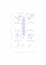
First lay out on 160 X 100 mm
Looks like single layers and no jumpers is possible.
Snags list
Rather long track return from LEDS
Pain in the but to tighten the power devices to the sinks.
Still loads of work to do but I would like to line up the power "transistors"
on the edge of the board.
I have a Pesante Dissipante which has already sinks fitted..
I can make boards much more simmetric than on firs lay out
Or maybe 2 boards for positive and negative rail.
I have used standard .6 W resistor size this will need changing maybe?
Attachments
Last edited:
On Trafos
I would like very much to use separate enclosure.
On atachments sorry for poor quality (limited file size)
I can email if needed...
PCB program I am using is Easy PC
Do not spend money on it as RS Components has a free download of same program which also has much beter library set
I would like very much to use separate enclosure.
On atachments sorry for poor quality (limited file size)
I can email if needed...
PCB program I am using is Easy PC
Do not spend money on it as RS Components has a free download of same program which also has much beter library set
Frans has 100uH instead of 100mH in his schematic.
Regards, Loek
Ahhhh that is a mistake, there is also a link to the actual component in the post and the schema, these are correct.
The correct value is 100mH.
Sorry for that.
Regards,
Frans.
Attachments
Hello Frans,
Is there a reference to the original article with the transformer plus common mode choke before the rectifiers, on the soundhost pages I only see general info on transformers.
Btw, in a bridge you have always 2 diodes in series, and also the snubbers if you place them across each diode. You can therefore replace four RC snubbers with a single one. Also, the snubber resistor value needs to be in the right ballpark to be effective. I would refer to the classic Hagermann article with formulas but I have no idea how the extra choke interferes with the transformer
Hi Frans,
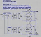
why do you use two bridges? Since we use a shunt reg, both polarities would sink the same current, so no imbalance can occur.
Rüdiger
It's just the way I use to do it. Normally I will use bridges like these:
3N255 Fairchild Semiconductor Bridge Rectifiers
They are 30 cents each and are (unavoidable) bridges
") and they sit here in a little box, ready to use.
and they sit here in a little box, ready to use.Hi Frans,
why do you use two bridges? Since we use a shunt reg, both polarities would sink the same current, so no imbalance can occur.
Designing a 'high end' and high quality power supply should not compromise anything, having separate bridges for both supplies is a sign of quality that should not be removed (just to spare a few euro's).
Hi Frans,
why do you use two bridges? Since we use a shunt reg, both polarities would sink the same current, so no imbalance can occur.
Bottom line, this is the way that I would do it
Regards,
Frans.
Hello Frans,
Is there a reference to the original article with the transformer plus common mode choke before the rectifiers, on the soundhost pages I only see general info on transformers.
Btw, in a bridge you have always 2 diodes in series, and also the snubbers if you place them across each diode. You can therefore replace four RC snubbers with a single one. Also, the snubber resistor value needs to be in the right ballpark to be effective. I would refer to the classic Hagermann article with formulas but I have no idea how the extra choke interferes with the transformer
No there is not, this is what Joachim and I (and others) do think will be a good, solid and high quality 'raw' power supply (pre regulator). The reference is intended to give some information (for those that need it) about wiring (and other) issues.
Hi Frans,
it's ok for me when you say it's your way, but it ain't, when you say it's the best, which it isn't (has been a topic at diyaudio now and then).
Rüdiger
Where did I say it's the best? No single design will ever be 'the best' and I would never claim to have designed 'the best' of anything. If I did so, then sorry for that. All designs will be a compromise between cost, quality, technology and time (there may be more factors).
Hi Frans,
my point is, the more complicated dual rectifier bridge is not better, it's worse technically. A exception might a situation where current needs of both polarities are very different. But doesn't apply here since we use shunt regs.
http://www.diyaudio.com/forums/power-supplies/161865-dual-bridge-ps-does-phase-secondary-matter-3.html is the thread I'm referring to.
No bashing or anything implied!
Rüdiger
Hello Frans,
Is there a reference to the original article with the transformer plus common mode choke before the rectifiers, on the soundhost pages I only see general info on transformers.
Btw, in a bridge you have always 2 diodes in series, and also the snubbers if you place them across each diode. You can therefore replace four RC snubbers with a single one. Also, the snubber resistor value needs to be in the right ballpark to be effective. I would refer to the classic Hagermann article with formulas but I have no idea how the extra choke interferes with the transformer
This is the Hagerman paper you refer to I think
http://www.hagtech.com/pdf/snubber.pdf
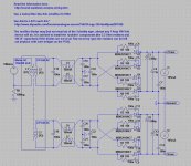
My first impression is, the values he is getting from his calculations seems very high for the resistors and very low for the capacitors. Understand me good, I am not saying he is wrong, but it is not in line with other information I have and (what I see as) general practice, including ‘rule of thumb’ values that we always used (and use).
So I went back to my reference books (Philips, International Rectifier, Motorola, National and Rifa), most of the material advices snubbers for ‘high power’ applications (that is into the KW’s). Values for snubbers are, near 5 Ohm for the resistor and 1 uF for the capacitor. None of the references (that I have) give any formulas or other hints to get at values (like tables or graphs).
Using these as an starting point I would say, 50 Ohm and 100 nF in our application. True enough, the 50 Ohm is more in line with the values that Hagerman would advise, the 100 nF is still way larger than the values he would recommend.
The Rifa information is also reveling. They would advise to use a component from the PMR2026 and/or PMR209 product lines. In there application note they are using 100 Ohm and 100 nF devices.
From these I would conclude that we need to change the current schema. I would like to change the snubber as specified to 100 Ohm and 100 nF.
We will use separate devices (resistor/capacitor). Using the PMR209 as available from (for example) Mouser seems to be very expensive (lowest priced PMR209 100 nF device about 4 Euro’s).
Mouser Electronics - Electronic Component Distributor pmr
Hi Frans,
my point is, the more complicated dual rectifier bridge is not better, it's worse technically. A exception might a situation where current needs of both polarities are very different. But doesn't apply here since we use shunt regs.
http://www.diyaudio.com/forums/power-supplies/161865-dual-bridge-ps-does-phase-secondary-matter-3.html is the thread I'm referring to.
No bashing or anything implied!
Rüdiger
The information that I have show’s that using half bridges is ‘no problem’ or ‘just as good’ as using full bridges when loads are equal. I still cannot see (and find any information) that using full bridges will compromise the design in any way. My conclusion is, we use full bridges (at maybe a very small cost) and we have a universal design model (implementation) that can be applied to any situation (being equal or unequal loaded).
For the moment I will leave the full bridges in place, if anyone can supply evidence of problems with this approach I will revise the schema.
No bashing or anything implied!
Non taken
Hi Frans,
you can't build bridge rectifiers with MBR20100CT. This is a three pin device with two diodes, cathodes connected.
And it is 20A, 100V - maybe a lttle above what's needed.
It is just an example selected from the ones available in LTspice
as stated in an earlier post I think that the 3N255 would be a good choice.Even an device as benign as the 1n4002 (5 Euro cents) would work in this application.
http://de.mouser.com/Semiconductors...xpqqZscv7?Keyword=1n4002&Ns=Pricing|1&FS=True
Last edited:
I think the idea to use double bridges is that it avoids the circulation of direct current though the transformer windings when the positive and negative rail load currents are different. This may not be the case here because we work in class A and have the shunts.
Still the current in the shunts may not be absolutely the same in the plus and minus feed.
Another advantage of the double bridge is that the rectifier current pulses for each half of the supply do not circulate though ground but rather circulate locally. This can improve management of rectifier noise. The transformer is only connected to the amplifier during the brief rectifier conduction intervals. That may reduce EMI ingress.
You can find this information in Bob Cordells Book " Designing Power Amplifiers ", from page 343.
My first impression is, the values he is getting from his calculations seems very high for the resistors and very low for the capacitors. Understand me good, I am not saying he is wrong, but it is not in line with other information I have and (what I see as) general practice, including ‘rule of thumb’ values that we always used (and use).
I took the Hagerman paper to be correct but I can't prove if he is right or wrong. And yes, there are many examples whith low resistance values floating around on the WEB, though I do get the impression that this is just a chain of copies. There was a paper on snubbing shottky diodes (possibly from IRF, can't find it right now) that showed what happens if the resistor value is (much) too low, namely that the RC snubber acted like a pure capacitor and would not snub. The best way to find out off course is to measure the live circuit and see the effect of different resister values on the turn off spikes, this way you can tune the value to it's optimum. I am not sure if anyone wants to go to that lenght. I once looked at turnon spikes in a supply by placing a simple pickup coil on top of a toroid transformer (air coil from crossover connected to a scope probe, but there may be better ways) and I could clearly see the spikes, though I did not play with snubber values (I was checking the effect of a small C in front of a LC input filter and found some hefty resonances).
Last edited: