a little teaser.....
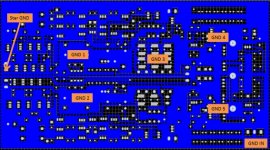
Here a screenshot of the ground plane arrangement.
on the left side is the (input) star ground connection
lower righthand corner is where the power input is connected
GND1 and GND2 are the ground connections of the input elcaps and cascode voltage filtering (including the zener string etc)
GND3 is the ground connection of the RIAA filtering components
GND4 is the ground connection of the positive shunt regulator
GND5 is the ground connection of the negative shunt regulator
GND1,2,3 are connected with wires to the star ground, whereas GND4,5 are connected through their ground planes
Honestly, I've tried my best. But I am open for any suggestions or improvements, just let me know!
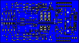
Attachments
@Hesener:
Thanks you very much for your efforts. Mind posting a bigger version of that ground layer pic?
And, even more important: You might want to avoid the jpg format for graphics. Jpg always gives blurred results on those. Try an indexed color format like gif or png.
Thanks you very much for your efforts. Mind posting a bigger version of that ground layer pic?
And, even more important: You might want to avoid the jpg format for graphics. Jpg always gives blurred results on those. Try an indexed color format like gif or png.
@Hesener:
Thanks you very much for your efforts. Mind posting a bigger version of that ground layer pic?
And, even more important: You might want to avoid the jpg format for graphics. Jpg always gives blurred results on those. Try an indexed color format like gif or png.
ooops, thanks for this tip!! the png file (although hires) is only 40kb.......
Attachments
Looks very good and I like the idea of connecting GND by wire... One question.... Why the star gnd at the input ?
I am using star gnd at the output (on the output RCA´s) with great hum reduction results.
PS JG: Luck is an atitude.
I consider myself lucky and I am glad you do not think I am blind...
I was unhappy because I lost the meaning during translation and I thought you meant: "Deus dá nozes a quem não tem dentes" "God gives nuts to those who have no teeth"
Now I know you did not mean that")
I am using star gnd at the output (on the output RCA´s) with great hum reduction results.
PS JG: Luck is an atitude.
I consider myself lucky and I am glad you do not think I am blind...
I was unhappy because I lost the meaning during translation and I thought you meant: "Deus dá nozes a quem não tem dentes" "God gives nuts to those who have no teeth"
Now I know you did not mean that
Last edited:
One more bad joke : the most stupid farmers have the biggest potatoes
No that is really awfull
Imagine a stupid blind chicken full of goodies. It might be dangerous.
Anyway, I got my trannies from Frans as well as Salas and ours are ok... Nothing to do with luck I guess.
Compensation maybe for something they lost. Also older people have usually more money then young ones when i trust the statistics.
Well it is a pitty that those machines are so expensive. One needs to work a whole life to be able to reach them. "Falo extensions?"
 Plus it has shunts with leds and 9240s which I am kinda fond of...for some reason.