O... I see.... that weird old man that tends to intrude into people´s houses through the chimney... I wonder how he fits in those small holes and never gets dirty 
Anyway your work is one of the best christmas presents one should hope for.
Looking good.
PS: why two outputs ?
Anyway your work is one of the best christmas presents one should hope for.
Looking good.
PS: why two outputs ?
Last edited:
I have not made the buffer as a stand alone,,, But i believe performance would be great.
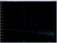
Here you can see that it has very very low distortion and no high-order elements.. and on the distortion plot it almost invisible...blue trace is pre-buffer and green is after...
It does have an offset of app 15 mV that has to dealt with if used as a standalone-buffer...
Here you can see that it has very very low distortion and no high-order elements.. and on the distortion plot it almost invisible...blue trace is pre-buffer and green is after...
It does have an offset of app 15 mV that has to dealt with if used as a standalone-buffer...
Attachments
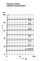
The buffer works well because the modulation of the 3 most important distortion sources is small. I already mentioned Early Effect. That is modulation of base current over Vce.
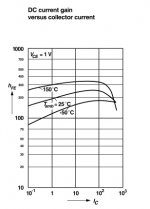
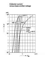
The chosen BC327, 337 are superb in that regard. The base current does not change much with varying Vce. We see a nearly straight line. Then we have casdoding and then we have a stiff supply. Second is modulation of Hfe over collector current. First the BC327/337 has a relative straight Hfe curve and then we have tremendoes current regulation from the precision current mirrors. Third is modulation of Ube, the voltage that appears between base and emitter, over collector current. That is in this buffer direct in the signal path. First we stay under 10mA where the curve is rather steep and then again the current mirrors hold the collector currents steady. The driven cascode transistors are a bit harder to explain : the input transistors drive the gates of the output transistors and the gates of the cascode transistors. Should any undesirable modulation happen the driven cascodes give that information to the input transistors in anti phase. One could also call that a bootstrap. This is a mighty fine buffer.
The chosen BC327, 337 are superb in that regard. The base current does not change much with varying Vce. We see a nearly straight line. Then we have casdoding and then we have a stiff supply. Second is modulation of Hfe over collector current. First the BC327/337 has a relative straight Hfe curve and then we have tremendoes current regulation from the precision current mirrors. Third is modulation of Ube, the voltage that appears between base and emitter, over collector current. That is in this buffer direct in the signal path. First we stay under 10mA where the curve is rather steep and then again the current mirrors hold the collector currents steady. The driven cascode transistors are a bit harder to explain : the input transistors drive the gates of the output transistors and the gates of the cascode transistors. Should any undesirable modulation happen the driven cascodes give that information to the input transistors in anti phase. One could also call that a bootstrap. This is a mighty fine buffer.
Attachments
you bet.....
here are the schematics of the preamp and regulators, please take a look if everything is correctly captured. I will start floorplanning with these versions now. I believe the consensus was that the transformer, rectifier and bulk caps are supposed to be in an external enclosure, correct?
enjoy.....
Checked the main (preamp) part. It is correct to my eyes. Along with update from MiiB in #3788 - I can see no flaw to your capture... Maybe others would also confirm.
I will report PSU part a.s.a.p.
Checked the main (preamp) part. It is correct to my eyes. Along with update from MiiB in #3788 - I can see no flaw to your capture... Maybe others would also confirm.
I will report PSU part a.s.a.p.
When checking the PSU note the eratae in 3772 and 3773.
When checking the PSU note the eratae in 3772 and 3773.
Thank you Frans for pointing these two out. Missing on capture.
Could also you please explain what is the background for advice in #3549?
Hesener - could you please update your capture if not already done with these details?:
FdW; said:R105/205 originaly 500 Ohm kan be 470 Ohm
R106/206 should be 2K or 2K5 trimmers to adjust the output voltage
FdW; said:Also change the BC550/560 to BC327/337, that is more in line with preamp. Just for fun
Thank you guys! Apart for above details the PSU capture is also fine.
Could also you please explain what is the background for advice in #3549?
You can ignore that, we resolved this by using only LED's for the reference.
I have not made the buffer as a stand alone,,, But i believe performance would be great.
Here you can see that it has very very low distortion and no high-order elements.. and on the distortion plot it almost invisible...blue trace is pre-buffer and green is after...
It does have an offset of app 15 mV that has to dealt with if used as a standalone-buffer...
Hi Michael
Thank's, I understand that you haven't analysed the buffer alone, I just wanted to compare the simulations of your buffer with my new buffer
God Jul
Stein "Bob Bob Bob" Nåså
")
Attachments
Thank you Frans for pointing these two out. Missing on capture.
Could also you please explain what is the background for advice in #3549?
Hesener - could you please update your capture if not already done with these details?:
Thank you guys! Apart for above details the PSU capture is also fine.
hi mad_z,
yes that is all implemented, no worries - i just hadnt reposted the updated schematic. but in the floorplan you will see already e.g. the trimmers...
also in the process of putting test points to check voltage levels and put the scope... any preferences on where to put them?
ricardo, if you so desire you could simply not stuff the shunt reg components, and connect your external PSU to the corresponding pads of the MOSFETs in the shunt regs - would that work for you?