

If this ones work it would be good. They are inexpensive :ZD 3,9 - Zener-Diode 1,3W 3,9V - Z-Dioden, 1,3W bei reichelt elektronik
Hi all,
layout work will start tomorrow, I am going with the schematic of post 3688 at this point - should be good enough for starting. I will be making place for 1/2W resistors, big input caps and some larger resistors where indicated. Plus, of course, the shunt regs.
Speaking of which - Frans could you give us an estimate of the power dissipation of the regulators, for choosing an appropriate heatsink?
Hi all,
layout work will start tomorrow, I am going with the schematic of post 3688 at this point - should be good enough for starting. I will be making place for 1/2W resistors, big input caps and some larger resistors where indicated. Plus, of course, the shunt regs.
Speaking of which - Frans could you give us an estimate of the power dissipation of the regulators, for choosing an appropriate heatsink?
These are the numbers:
D45H11/D44H11 1.7W
LM317/LM337 0.7W
IRF610/IRF9610 1.1W Under normal (105mA) load condition
IRF610/IRF9610 3.6W When preamp disconnected
This is for a 24Vac transformer, for every Vac rise on the transformer the power consumption of D45H11/D44H11 will rise with about 250mW.
That was quick Frans, thanks a lot!! These numbers are not very high but high enough in my opinion to merit a good heatsink.
Three options:
- locating the power components on the edge, so they can be attached to an external heatsink
- (several smaller) heatsinks that can be soldered onto the PCB
- one larger heatsinks (e.g. 80mm) that goes across the PCB and all power components are attached (requires isolation pads)
opinions?
That was quick Frans, thanks a lot!! These numbers are not very high but high enough in my opinion to merit a good heatsink.
Three options:
- locating the power components on the edge, so they can be attached to an external heatsink
- (several smaller) heatsinks that can be soldered onto the PCB
- one larger heatsinks (e.g. 80mm) that goes across the PCB and all power components are attached (requires isolation pads)
opinions?
Shared heat sinks is best, option one or three. Option two is problematic due to the different wattages being dissipated, needing different sizes.
Option 1 or 3 needing heat sinking for about 6Watts.
This can be done on the PCB (6Watt), so I would go for option 3.
Under normal conditions (preamp connected) 3.5W is being dissipated. I would go for +20 degC (above environment) and that would need a 5 or 6 degC/Watt heat sink. That sets an (acceptable) temperature increment of about +30 degC when the preamp is not connected.
Last edited:
1N829 stock
I've made a phone call to the supplier and he confirms web page stock status.
I am more into BZX85C type also but if anyone is interested in 1N829 for other project I may provide either contact details or even organize some buy.
The final cost including VAT tax is 0.78EU per 1pc.
---------------
I will check today my 'stock' - I am pretty sure I have BZX85C at hand - these could be tested by anyone who has equipment accessible.
I must admit it has been some years since I checked pricing on these, I just stopped using zeners altogether but if prices have come down to those figures Ill have a second look at those parts.
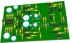
I am using Design Spark from RS.... it is freeware and can be downloaded from RS site.
It has the transistors but is very limited in the zeners and caps. Anyway, it is very easy to use and produces nice 3D images. Good for looking before starting p2p.
If I would be working for a pcb, it would need 3 or more layers (2 lines plus GND plane)... I am using shunts right now.
The best part is that you introduce the schematic and the pcb screen is linked so we can move parts and the connections are always according to the schematic.
I had some trouble to place the mirror´s upper transistors face to face but in the end I figured it out.
Today I will be looking at the GND layout.
Anyone knows what is a thou (measure unit) ?
It would be much better if I could set the grid spacing to 2.54mm
Hi mad-z
I really had issues with zeners but I know some are very silent, principally if not used in the avalanche zone. Why did you choose the BZX85C ?