Don't take it as critique, wasn't meant that way. I build something very similar some time ago, but with a resistor to ground (47k) at the input, hence my question.
I vote for minishunt for the ref-voltage, it's no big deal to make (but costs one jfet per rail...)
Rüdiger
I vote for minishunt for the ref-voltage, it's no big deal to make (but costs one jfet per rail...)
Rüdiger
Errata
Beis BF458, BF459
BF469, BF470
BF471, BF471
there are more HF trannies that work, also trannies with low saturation voltage
there is really no shortage of low noise bipolars but i would prefer the ones that have also high Hfe and high early voltage speed and linearity are also important
Beis BF458, BF459
BF469, BF470
BF471, BF471
there are more HF trannies that work, also trannies with low saturation voltage
there is really no shortage of low noise bipolars but i would prefer the ones that have also high Hfe and high early voltage speed and linearity are also important
MiiB, the 2SA1015, 2SC1815 combo is just fine. I use 4 plus 4 in the Opus Magnum and that one is also unbalanced because that has 3dB less noise for the same amount of input transistors against a balanced. Layout is the really important when we want to avoid hum. Can be done though. Sam has a phonostage of mine under evaluation that is unbalanced and dead quiet, no hum. The PSU is extremely elaborated though. The PSU is nether simple nor elegant. It is more a brute force approach. I told you, my PSU abilities are crippled.
Michael,our input stage has not much more then 5 Ohm noise impedance with the Toshibas. Better is simply not physically possible.
Michael,our input stage has not much more then 5 Ohm noise impedance with the Toshibas. Better is simply not physically possible.
Joachim,
Have you measured bc337 ? I had very good results in some RF applications. Found it by chance, as I had couple bags of them from leftovers in lab. I do not remember the details (numbers) now, but I needed lowest 10Hz-1MHz in band noise, and bc337 at my application current was best from all that I had in my zip box. It's just sad that I do not have access anymore to that nice Agilent E5052B, could measure some...
P.S. Google seems to confirm this.
Yes, this one works too. I realized that i had your file on my computer already because i had to override it when i stored it. Thats what i say, there are a lot of bipolars that are low noise into low impedances. Anyway, thanks for finding one more candidate.
Rüdiger, here is a 5mA current regulating diode. Unfortunately it is expensive so a Fet is actually more economical in this case.
1N5314 Central Semiconductor Current Regulator Diodes
Rüdiger, here is a 5mA current regulating diode. Unfortunately it is expensive so a Fet is actually more economical in this case.
1N5314 Central Semiconductor Current Regulator Diodes
Sampler, i looked more into the BC337 and think that is a real good find. This is even an NPN so the BC327 is potentially quieter. They are fast, have decent linear Hfe and a high early voltage. Better still the group 40 version has rather high Hfe. A rare find in low noise Bjts. The champions are the Hitachis with over 600 but this ones are not so bad either.
The 2SA1015, 2SC1815 i have have a Hfe of around 180, useful but a bit lower. When we use this BCs in the Paradise Lost the input impedance will go up by a factor of nearly three.
That is true for the BC550, BC560 but they have a 5 times higher Rbe`.
I have ordered 100 pairs. They are inexpensive and better still in production from several makers like Vishay and Fairchild.
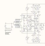
I have put the 2SA1015, 2SC1815 into the circuit, I have also degenrated the input some more with 47 ohms to improve distortion gain is now 55 dB but can be raised in the RIAA correction network.
I have removed the servo from this stage, The servo can later be fitted at the buffer..
I have also implemented the proposed shunt, but something unbalances the circuit so offset at the RIAA node is now 3V (with Zeners it was only 300 mV) the shunt stabilizes the voltages at the cascodes at app +-12 volts, but with at little difference at each rail...(in the ballpark of app 0.5V) could be I have an error in my implementation...??
I think it's important that we finalize the input/amplification stage, so we have that in a good balance/working condition, then the buffer can be implemented.
Attachments
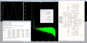
I found some models from NXP on the BC327-47/BC337-40. with those transistors the offset is minimal..(app 100mV) I do think the offset is generated in NPN/PNP differences in the current mirrors.
I made an distortion plot with 1 KHz and app 0.5 V out....Looks fine I think...
To simulate deep in the noisefloor I changed capacitor values to 1F...so pls don't take notice of that....
I agree, we must have some shunt support from those who know better...
I made an distortion plot with 1 KHz and app 0.5 V out....Looks fine I think...
To simulate deep in the noisefloor I changed capacitor values to 1F...so pls don't take notice of that....
I agree, we must have some shunt support from those who know better...
Attachments
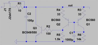
MiiB, here you are.
EDIT: I could provide you with a LTSpice-file where I use these if you like.
Rüdiger
Cute cuddly mini Reflektor.
")
I have also implemented the proposed shunt, but something unbalances the circuit so offset at the RIAA node is now 3V (with Zeners it was only 300 mV) the shunt stabilizes the voltages at the cascodes at app +-12 volts, but with at little difference at each rail...(in the ballpark of app 0.5V) could be I have an error in my implementation...??
Use a trimmer for the voltage reference resistor (the one bypassed with the big cap value) of the mini current mirror shunts. Using NPN/PNP changes Vref due to differences in Vbe. Vbe adds to Vref.