funny wit the gain issue.. in my simulations there is plenty....gain....
when working with current inputs, there is no reasons to set the impedance with additional resistors, as the coil impedance will set the loading...so off course carts with low current output and lowish generator impedance will have low output...
could it be possible to increase the voltage swing on the input fet by adding some series resistance..???
I see it the following way : a cartridge with low impedance will enjoy more gain then a cartridge with high impedance. My Titan i has around 6 Ohm, the DL103 has around 40 Ohm. The Denon will provide more current feedback so the gain goes down. But maybe the distortion too. I assume the input impedance of the Starless is around 20 Ohm. If you add a series resistor of say 34 Ohm to the Titan i we will have the same situation then with the Denon. Less gain and less distortion. Unfortunately the Johnson noise goes up too because the 34 Ohm is in series with the signal. The possible output swing will not change. It is set by the voltage over the Fet cascode input stage. In this case plus-minus 12V. Pick your poison, or do you have a better explanation ?
Yes
Yes.
As a general rule a mc cart with low impedance has low
output and vice versa. This is true for most, but not all.
So any mc current input stage will act in the right way
as far as amplification is concerned.
Damping can be changed by inserting the mentioned
series resistors. But for me it seems that the damping
or mc "loading" issue is overemphasized and it is different
with a current input if compared with resisitive loading.
So do not stick to recommended resistive loading values -
better experiment yourself.
No
No, I do not think this is a feedback mechanism.
Anybody here able to calculate that or verify by
clever simulation?
Thanks.
The Denon will provide more current feedback so the gain goes down. But maybe the distortion too. I assume the input impedance of the Starless is around 20 Ohm. If you add a series resistor of say 34 Ohm to the Titan i we will have the same situation then with the Denon. Less gain and less distortion.
No, I do not think this is a feedback mechanism.
Anybody here able to calculate that or verify by
clever simulation?
Thanks.
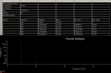
Maybe it is a simple voltage divider. 20/6 = 3.33... 20/40 = 0.5
3,33../0.5 = 6.66... that would explain the gain difference that amounts to over 12dB.
The Denon has strange parameters anyway. Quite high impedance plus low output. The Clearaudios are somewhat better but not much. Clearly not optimized for lowest Johnson noise to begin with, even in a traditional transconductance design. Contrast that to the My Sonic Lab Eminent with less then 2 Ohm and 0.5mV. The EMTs are somewhat in between with 20 Ohm and 1mV.
Contrast that with the Eminent. Noise is 0.65nV/qHz less and level is 5dB more. They even make a better one that has even less impedance with the same output. There must be some really strong magnets at work here, maybe with a cobalt armature.
Attachments

Sampler, do you use any decoupling on the Lithium cells ? I can only see small decoupling caps on the board.
Yes, I added 4 x 1000uF Panasonic FM for listening test. But I leave out PSU options for later. Probably single shunt and separate cap multipliers for every rail of gain stages. I really don't fancy all "what cap sound best" games. I almost finished second op-amp stage, the one with a buffer, maybe I will give it a listening tomorrow. Btw servo opamp is missing a cap in that schematic. It's not a big deal
")
Yes it is, but that changes when you replace voltage source with real cart model.funny wit the gain issue.. in my simulations there is plenty....gain.... when working with current inputs, there is no reasons to set the impedance with additional resistors, as the coil impedance will set the loading... could it be possible to increase the voltage swing on the input fet by adding some series resistance..???
I don't think so. You are either adding additional resistance to cartridge or degenerating the upper input pair - gain goes down.
It depends on how you look at it. One way is to say you are operating voltage source with its finite impedance (45Ohm,~80uH for DL103) to the virtual ground, with finite resistance of ~15 Ohm (for my batch of fets). Source impedance is limiting maximum current that you can supply to virtual ground and as a result gain goes down. Can we call it some mechanism of current feedback ? Well I'm not sure. At least not after reading all the debates in JC thread on what can be called feedback and what can'tNo, I do not think this is a feedback mechanism.
Anybody here able to calculate that or verify by clever simulation?
Thanks.
I would call it local degeneration. To prove that theorem we would have to simulate distortion. When it goes down it is equivalent to shunt feedback in an Opamp.
Sorry i missed the cap in the servo. I am multitasking at the moment and i was much better on this when i was young. I cooked me some pasta with tomatos, i baked a bread and i build the electronics for the L`Art du Son Buffalo Bill line stage that has to be ready in some days for the Vienna Klangbilder show. Keeps me alive.
Sorry i missed the cap in the servo. I am multitasking at the moment and i was much better on this when i was young. I cooked me some pasta with tomatos, i baked a bread and i build the electronics for the L`Art du Son Buffalo Bill line stage that has to be ready in some days for the Vienna Klangbilder show. Keeps me alive.
I find it interesting technically. There will be a new top Lyra called the Atlas. It has a cross armature instead of a square. First prototypes had 0.9mV output with 6 Ohm. Guess what ? In series production it was decided to drop the output to 0.5mV because some very high gain stages that are common today ( i have seen 70dB and more ) could be overdriven.
I would really like to have that prototype.
I would really like to have that prototype.