Yes, with that trim you can null distortion. It also affects offset and when you have the right Fets you can null that with this trim too. It fluctuates a bit though because the Fets have a temp co. How does the Rabbit Hole sound and does it work properly ? I think it is a great circuit, a classic.
You mean in the shop, in Japan for example, 30.000,-€. It´s totally over the top. Making it is around 6500,.€. You can reduce cost a lot by using other resistors and caps and making a less elaborate PSU. The absolute minimum would be 2000,-€ material cost i assume without too many compromises.
Woooh...
That is expensive, I could manage the DIY priced option, 2000€ certainly isn't out of reach for a project that takes a few months. If you ever decide to make pcbs available, please let me know, even if I have sign a none disclosure agreement ;-)
Simon
www.bestkiteboarding.com
That is expensive, I could manage the DIY priced option, 2000€ certainly isn't out of reach for a project that takes a few months. If you ever decide to make pcbs available, please let me know, even if I have sign a none disclosure agreement ;-)
Simon
www.bestkiteboarding.com
Hi Simon !
A lot of the cost is in the pre-regulator i posted. If you use a more conventional supply and use normal metal film resistors plus less expensive caps ( no Black Gates, Silmik2, Mundorf Silver-Gold-Oil ) and no metal can LME49710, OPA627 you can cut the cost down to maybe 500,-€. Also for the PCBs i used Isola G200 that is also expensive. I am planning a run of 10 FR4 PCBs that also will cut the cost down. When i get this PCBs i will post it on this forum. I could then supply the PCbs plus circuit diagram and construction hints. The transistors have to be selected so just stuffing the board does not work. It creates a DC offset that sets up the second stage so it is not easy to build it without instructions.
A lot of the cost is in the pre-regulator i posted. If you use a more conventional supply and use normal metal film resistors plus less expensive caps ( no Black Gates, Silmik2, Mundorf Silver-Gold-Oil ) and no metal can LME49710, OPA627 you can cut the cost down to maybe 500,-€. Also for the PCBs i used Isola G200 that is also expensive. I am planning a run of 10 FR4 PCBs that also will cut the cost down. When i get this PCBs i will post it on this forum. I could then supply the PCbs plus circuit diagram and construction hints. The transistors have to be selected so just stuffing the board does not work. It creates a DC offset that sets up the second stage so it is not easy to build it without instructions.
Hi Simon !
A lot of the cost is in the pre-regulator i posted. If you use a more conventional supply and use normal metal film resistors plus less expensive caps ( no Black Gates, Silmik2, Mundorf Silver-Gold-Oil ) and no metal can LME49710, OPA627 you can cut the cost down to maybe 500,-€. Also for the PCBs i used Isola G200 that is also expensive. I am planning a run of 10 FR4 PCBs that also will cut the cost down. When i get this PCBs i will post it on this forum. I could then supply the PCbs plus circuit diagram and construction hints. The transistors have to be selected so just stuffing the board does not work. It creates a DC offset that sets up the second stage so it is not easy to build it without instructions.
Is there any worthwile sonic improvement in using metal can mentioned op-amps compared to normal plastic package?
Last edited:
I experienced a very small difference. Certainly under the resolution of a controlled experiment. Like swapping ( decent ) cables and such. The OPA627 is used as servo so in that position an OPA134 in any package will do. The OPA827 will give even lower offset
then the OPA134. The LME49710 in metal can is not that super expensive so you could give it a shot. It looks mighty pretty on the board though.
then the OPA134. The LME49710 in metal can is not that super expensive so you could give it a shot. It looks mighty pretty on the board though.
In the position where the LME49710 is there is also the possibility to use an SMD Opamp.
An LME49990 could be used that arguably out performs the LME49710 so you can save money when substituting the metal can LME49710 and gain performance at the same time. Is that good ?.
An LME49990 could be used that arguably out performs the LME49710 so you can save money when substituting the metal can LME49710 and gain performance at the same time. Is that good ?.
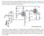
PEN MC Head Amp
Recently Euvl published two very simple I/U converters called CEN for complimentary and SEN for single ended. Based on the Pass ZEN converter he uses a floating PSU for improved performance. He claims an improvement of 6 times less distortion over the ZEN that has low distortion to begin with. This is really astounding for a circuit that simple. Having used transconductance circuits with Fets myself and knowing from Malkolm Hawksford that an I/U converter can also serve as an MC input stage i had the idea to modify his circuit a bit to be useful as an MC head amp. It occurred to me that the circuit can be setup DC coupled too. I particular like the SEN because it does not need the rare P Channel JFets. I build a circuit in 5 minutes with parts i had without selection.
It worked right away. I measured a DC offset at the input of 10uV. That can be lowered by selecting IDss or can be trimmed away in the current source. At the output i measured 200mV DC offset with 470 Ohm resistors but that can also be trimmed away.
The circuit shown has that trim. The gain is around 120 x , that is more then 40dB. That is a lot and i thought immediately if that stage with some modifications can be used as the input stage of an AIOG RIAA. I am not so far yet but i have an idea to improve it that also could help the original design. By the way i measured the upper -3dB limit as 200kHz so G/B is around 2MHz. A 10KHz square wave looked clean. So here it is : the most simple MC input stage i ever build. I will listen to it the next day.
Attachments
The BF862 is cheeper and in production. The circuit is dimensioned for 2SK170, one each for amplification and constant current source. If you use 2SK170 with IDss 9mA and you use a 9V block battery after Kirchhoff´s law you end up with two 500 Ohm resistors hence the 1kOhm trim pot. Then all current that flows in the Fet´s also flown in the resistors. If you use 2 x 2SK170 each or one BF862 each you have to lower the resistors in half. Unfortunately i can not get the DC offset stable so you have to insert a 1uF cap after the trimmer when the next stage input impedance is 47kOhm. I have noticed that Euvl thermo couples the Fet`s. I have not tried this and it should stabilize the DC offset. If that is good enough for DC coupling i do not know but i will try. I also think that the amplification is a lot higher then i want. The only way to get that down is AC couple like Euvl and then put a resistor from output to ground that makes the amplification factor adjustable by Gm x R. The Fets could also be suppled by resistors or constant current sources and DC coupling could be provided by folded cascodes but that destroys the simplicity of the circuit. The Fet´s could also be loaded by current mirrors and DC coupled that way. I have shown that before but again that is more complex. Give me some time and i can figure out if this circuit is usable. I have also not measured noise and have not listened. VF1 and VF2 are in and output. You have to add a ground connection in both cases.
Think It'll be very very good...like a Jfet version of Hiraga's Le prepre...")
Could be a nice target for a light based galvanic separated supply...The B862F does not need as much current as the SK170 to have good performance and low noise, they perform well at 2-3 mA.
http://www.lcaudio.dk/images/Accessories/mcstepbig.gif
http://www.farnell.com/datasheets/26602.pdf
SEE THE LIGHT.....!!
Last edited: