I know there are a few posts on this already but a lot of the schematic links in the threads are dead. I also found two schematics online that did not seem to have a mention on this forum:
http://www.angelfire.com/ca2/roderick/riaa/RIAA.htm
http://www.maxim-ic.com/appnotes.cfm/an_pk/1931
What do people think of these? I built the first one and of course the LM324 is not ideal but it doesn't sound too bad...however, the voltage spike on startup across C5 is killer, it forces my digi pot to lock up (and will possibly break it). The bass response doesn't seem to be all that great either..
The second link looks more ideal, especially since it is low voltage (the first link mentions that a lower supply voltage on the LM324 might cause output clipping).
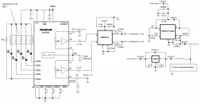
I'm building this for a Sony LX350H turntable to incorporate into my battery powered speaker system. I've attached a rough schematic of the setup.
If anyone knows any other simple single supply opamp phono preamps that might work better please post em here! and this might be a really dumb question, but what is the best use of the separate ground screw terminal? I figured to just join at the star ground point but would like to know if anyone knows something better.
http://www.angelfire.com/ca2/roderick/riaa/RIAA.htm
http://www.maxim-ic.com/appnotes.cfm/an_pk/1931
What do people think of these? I built the first one and of course the LM324 is not ideal but it doesn't sound too bad...however, the voltage spike on startup across C5 is killer, it forces my digi pot to lock up (and will possibly break it). The bass response doesn't seem to be all that great either..
The second link looks more ideal, especially since it is low voltage (the first link mentions that a lower supply voltage on the LM324 might cause output clipping).
I'm building this for a Sony LX350H turntable to incorporate into my battery powered speaker system. I've attached a rough schematic of the setup.
If anyone knows any other simple single supply opamp phono preamps that might work better please post em here! and this might be a really dumb question, but what is the best use of the separate ground screw terminal? I figured to just join at the star ground point but would like to know if anyone knows something better.
Attachments
They are both functional. This thing is by insisting on a single supply rail you've basically killed any chance of the circuit sounding decent.
Considering the time, trouble of building a DIY phono stage, the extra trouble of using split supplies is minimal and the benefit is huge.
If you've only got a single supply rail to play with, perhaps a discrete transistor circuit might be more appropriate. Op amps are best run with with split supplies.
thanks for the reply rjm. The reason why I am asking about single supply is because a dual supply is really impractical in my setup, since it is a portable 12v battery powered gainclone speaker system. Another battery would complicate things a lot with weight, charging, etc. However, I was thinking about using a CR2032 for a -3v input given that it would last long enough...what do you think?
I also ordered some nice opamps that are single supply, namely the OPA211 and TLC2274 since it's a drop in replacement for the LM324 and looks to be much better.
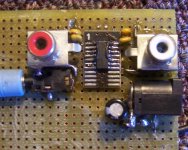
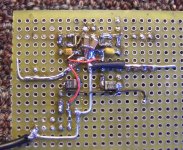
I finished building the first circuit and attached some pics. I like it because it is really basic and the noise isn't so bad even with the LM324. Only major fault I'm noticing with it now is some distortion in the very high frequencies, >15k when a musician makes an 'sss' or 's' sounds at the end of words, like "billie jean i"s" not my lover" (lol)
Do you know if the first circuit is true RIAA and/or what db differences there are? Or can you say if the second circuit is better? Thanks for your help.
I also ordered some nice opamps that are single supply, namely the OPA211 and TLC2274 since it's a drop in replacement for the LM324 and looks to be much better.
I finished building the first circuit and attached some pics. I like it because it is really basic and the noise isn't so bad even with the LM324. Only major fault I'm noticing with it now is some distortion in the very high frequencies, >15k when a musician makes an 'sss' or 's' sounds at the end of words, like "billie jean i"s" not my lover" (lol)
Do you know if the first circuit is true RIAA and/or what db differences there are? Or can you say if the second circuit is better? Thanks for your help.
Attachments
The LM324 seems OK, I'm not about to simulate it to find out if the RIAA values are correct, they look ballpark reasonable and I assume the designer did his/her homework.
The odd thing is the bias network R1 R2. 470k 47k split puts the input at only 1/11 th of the power supply voltage, 2 V in the case of the original design, but you've only got 12 V power supply so the input is at 1 V. That's too close to the negative power supply terminal of the opamp, and very likely the source of your distortion.
Try 100k for both R1 and R2, that give an input impedance of 50k and biases the input stage at 1/2 the power supply.
MC cartridges are rare, so it's unlikely that you have one.
Audioxpress did a comparison of budget phono preamps a while back; it includes schematics of them too:
http://www.audioxpress.com/reviews/media/403hansen2090.pdf
Audioxpress did a comparison of budget phono preamps a while back; it includes schematics of them too:
http://www.audioxpress.com/reviews/media/403hansen2090.pdf
rjm thank you for the recommendation on the Biases. It seems to have helped. The other big help was swapping out that crummy LM324 for the newer pin-for-pin compatible TLC2274 opamp. Of course you were right about having dual supply rails, it sounds much better with this as well. It's operating at +-5v right now which I hope is not too low for this circuit (seems to sound fine). Only problem right now is the ICL7660 output is not regulated and since I don't have Maxim's better version of the chip, it is using a built in oscillation frequency within audible range. So there is an annoying constant high-pitch buzz from that. Once I order the new chip this should be resolved.
I am also thinking of building your phono preamp using some of these newer opamps I have (like OPA211). Do you think it will be a big improvement in quality?
Dangus, thank you for the MC note. And that PDF is perfect, it has so many wonderful schems which I can try now (and are likely much better than this circuit")
I am also thinking of building your phono preamp using some of these newer opamps I have (like OPA211). Do you think it will be a big improvement in quality?
Dangus, thank you for the MC note. And that PDF is perfect, it has so many wonderful schems which I can try now (and are likely much better than this circuit
Hey all,
I updated the circuit with a OPA211 and it was a nice improvement. I also dropped with ICL7660 for the MAX1837 (DC-DC conv with an inverting output) and that fixed the humming.
Only problem now is that the "s" sounds still seem distorted, so I am guessing it goes off RIAA in the higher frequencies. I could make some recordings on my computer if anyone think that would help. Any recommendations to fix this would be really nice so I don't have to build a new setup from scratch :/ I'm getting 2.2v on both inputs after biasing with 100k from +5v to ground with a +4.4v and -3v power supply. Tried a -5v supply and distortion is still there..
They are both functional. This thing is by insisting on a single supply rail you've basically killed any chance of the circuit sounding decent.
Considering the time, trouble of building a DIY phono stage, the extra trouble of using split supplies is minimal and the benefit is huge.
If you've only got a single supply rail to play with, perhaps a discrete transistor circuit might be more appropriate. Op amps are best run with with split supplies.
Split supply means dc coupling of the moving coils (without any capacitors in series and therefore without DC protection)
What kind of DC protection do you use in the MC I/U converter (OP-27 without jFET input) in your phono clone from 47lab - go to
http://phonoclone.com/images/pc_cir.gif
in this case this thread could also be of interest:
http://www.diyaudio.com/forums/anal...ltage-before-coil-damaging-2.html#post1995449
Independent of this an "off topic" question: - do you have experience with the Plessey IC "SL 459", inside in a RIAA preamp special made for the cartridge "Blue Oasis"? - for inside circuit of SL459 go to
http://www.diyaudio.com/forums/anal...-blue-oasis-win-research-group-schematic.html
This head amp is one of the best sounded with no discrete devices (only SL459 + NE5534) inside.
Last edited:
okay so a friend let me borrow his great Stanton needle but the distortion is still there...so it is definitely the preamp.
I am using this preamp: RIAA Preamp
I'm using a +-5v supply with 4 OPA211 opamps.
I noticed the design is almost exactly the same as the one here:
- DIY Phono Preamp : Recording Magazine -
minus changes in the "rumble" filter settings for R3 and C3 and the input filter (R6 and C6) and the resistor (R12) instead of a 4.7uf cap on output.
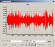
I attached a picture using wave splitter to see if clipping is occuring and it looks like it clearly is (30k to -30k) and I'm wondering, would this account for the distortion?
Also, since i am using a split supply I put 100k resistors between each voltage and the opamp input (substituting for R1 and R2 in the first schem) however, since I am using a dual supply I don't know how to change the values without messing up the RIAA curve. The first link says:
"To adjust the gain of the amplifier without sacrificing the RIAA equalization response, scale both R1 and C4 together as a set, and R3, R5, C2, and C3 together as a set, remembering that a capacitor's impedance is inversely proportional to its capacitance, at any given frequency. For instance, if you needed to halve the gain, you could double R4 to 3k (2.7k or 3.3k are practical values), and halve C4 to 11 uF (10 uF). Or, you could halve both R3 and R5, while doubling C2 and C3. "
This confuses me though since he says I can just double R4 and halve C4 after saying I need to scale much more than that.
So I have a couple questions:
1) could the 'lower' +-5v supply be causing the clipping?
2) should I just change the circuit to the second schem (is it better)?
3) do the input bias 100ks have anything to do with the clipping?
4) should doubling R4 and C4 fix the problem per his suggestion (since I am biasing differently)?
Thanks for any help on this! I'd be glad to upload an audio clip for anyone to listen to the distortion I am talking about if it would help (I would need to find a site for it too since I cannot attach it here).
I am using this preamp: RIAA Preamp
I'm using a +-5v supply with 4 OPA211 opamps.
I noticed the design is almost exactly the same as the one here:
- DIY Phono Preamp : Recording Magazine -
minus changes in the "rumble" filter settings for R3 and C3 and the input filter (R6 and C6) and the resistor (R12) instead of a 4.7uf cap on output.
I attached a picture using wave splitter to see if clipping is occuring and it looks like it clearly is (30k to -30k) and I'm wondering, would this account for the distortion?
Also, since i am using a split supply I put 100k resistors between each voltage and the opamp input (substituting for R1 and R2 in the first schem) however, since I am using a dual supply I don't know how to change the values without messing up the RIAA curve. The first link says:
"To adjust the gain of the amplifier without sacrificing the RIAA equalization response, scale both R1 and C4 together as a set, and R3, R5, C2, and C3 together as a set, remembering that a capacitor's impedance is inversely proportional to its capacitance, at any given frequency. For instance, if you needed to halve the gain, you could double R4 to 3k (2.7k or 3.3k are practical values), and halve C4 to 11 uF (10 uF). Or, you could halve both R3 and R5, while doubling C2 and C3. "
This confuses me though since he says I can just double R4 and halve C4 after saying I need to scale much more than that.
So I have a couple questions:
1) could the 'lower' +-5v supply be causing the clipping?
2) should I just change the circuit to the second schem (is it better)?
3) do the input bias 100ks have anything to do with the clipping?
4) should doubling R4 and C4 fix the problem per his suggestion (since I am biasing differently)?
Thanks for any help on this! I'd be glad to upload an audio clip for anyone to listen to the distortion I am talking about if it would help (I would need to find a site for it too since I cannot attach it here).
Attachments
Last edited:
- Status
- This old topic is closed. If you want to reopen this topic, contact a moderator using the "Report Post" button.
- Home
- Source & Line
- Analogue Source
- Simple Single Supply Phono RIAA opamp preamp