Which/what is the referred schematic?Yes, Yes and Yes (as in the referred schematic)")
I think that there may be a shielding/grounding error in the first posts.
I think that there may be a shielding/grounding error in the first posts.
I really do not know what you mean, please comment in the Balanced input all DC coupled RIAA preamp thread if you have comments about that design.
Also: there have been 10 sets of boards build (board as shown in the thread) and no faults have been reported or found (until now
).Dear Frans,
Sorry for the late reply. I tried to deduct the esence from the Salas simplistic shunt regulator thread, but it is extremly long.
but you right, I have to choose.
And I will follow your suggestion;
I've just got an acceptable PSU modul from china with LM317 and TL431 and good quality capacitors, so I will build the phone amp with this, and later I will build a shunt reg.
I will check your links too and give feedback.
Szabolcs
I checked your links. Still I prefer the Salas v1.2. (3200th post) Here the voltage reference is basically a resistor which is feeded by a small CCS. Likely results a not very noisy output.
Since in your suggested circuit for the phono AMP there is a DC compensation, so if the PSU VCC or VSS is not extremly stable it shouldn't be a problem.
Sz.
Since in your suggested circuit for the phono AMP there is a DC compensation, so if the PSU VCC or VSS is not extremly stable it shouldn't be a problem.
Sz.
PS, anyway thanks for the collection, nice set of info, which can be used independently from the final circuit.
Good idea, start with a simple PSU and 'upgrade' later. Let us know of your progress
Hi Frans,
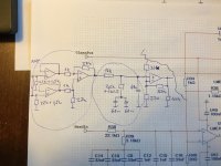
A very base try; on test PCB, mono, OPA2134 + TL081 as integrator.
but it also have some musicality.
I like this circuit.
I have only one question, why the R36 and R40 is so low impedance?
The C15+c16 has 234ohm impedance at 20kHz.
so the impedance equality on the OPAMP + AND - will be fullfilled just around 200kHz.
Or am I wrong?
Thanks,
Sz.
A very base try; on test PCB, mono, OPA2134 + TL081 as integrator.
but it also have some musicality.
I like this circuit
.I have only one question, why the R36 and R40 is so low impedance?
The C15+c16 has 234ohm impedance at 20kHz.
so the impedance equality on the OPAMP + AND - will be fullfilled just around 200kHz.
Or am I wrong?
Thanks,
Sz.
Hi (again
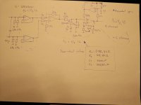
I think I will apply in the next test build the following input stage (enclosed pict): it solves the high resistor question. I found an riaa filter planning, which applies slighlty lower impedance. In the last stage I applied some higher resistance value. But since I put more amplification into the imput stage, here again no need to apply resistor with high value. The integratior part is the same.
I don't find, how can add pict?
Sz.
Hi (again
I think I will apply in the next test build the following input stage (enclosed pict): it solves the high resistor question. I found an riaa filter planning, which applies slighlty lower impedance. In the last stage I applied some higher resistance value. But since I put more amplification into the imput stage, here again no need to apply resistor with high value. The integratior part is the same.
I don't find, how can add pict?
Sz.
When editing a message press the paperclip button.
The RIAA? just go for it, it looks good.
Last edited:
Built circuit
Hi All,
Finally I built this circuit too. (attached the final version).
I used Wima Caps for the RIAA filter and 1% tolerant resistors (measured and selected).
The power supply is a SALAS one (in separated box).
I had an older NAD5120. The pickup is auditechnika ATN90.
I built the RIAA pream into the turntable' box itself (I now it is not the ideal place, but I wanted to minimize the cable length between the pickup and preamp.
Sound:
- for me the bass is too strong.
- Unfortunately the arm is not shielded (neither grounded so it collects some noise if I approximate with my hand to the arm (possibly the symmetric connection is not perfect here).
- I have to find an audiophile recorded LP to test the real soundstage
(I listened my old LPs - which were not the best recording (HU) )
I will try to test it with a better pickup.
Attachments
A passive RC filter (even if buffered before and after) cannot have high Q, because the network equations are all dissipative and 1st order (well, there are specific exceptions like twin-T notches).passive means that the eq correction is not built inside the amplifier stage(not in the feedback network of the op-amp gain stages)
Once you add feedback into the filter network you can define the network equations more freely (the two opamp inputs are defined as equal in most negative feedback situations, ie they create a new equation), which allows 2nd order behaviour, high Q, gain, oscillations even.
Passive filters using RC and L can have high Q, but cannot oscillate or have power gain.
Active filters need only R and C for arbitrary behaviour, meaning expensive, bulky, non-linear inductors are not needed.
A passive RC filter (even if buffered before and after) cannot have high Q, because the network equations are all dissipative and 1st order (well, there are specific exceptions like twin-T notches).
Once you add feedback into the filter network you can define the network equations more freely (the two opamp inputs are defined as equal in most negative feedback situations, ie they create a new equation), which allows 2nd order behaviour, high Q, gain, oscillations even.
Passive filters using RC and L can have high Q, but cannot oscillate or have power gain.
Active filters need only R and C for arbitrary behaviour, meaning expensive, bulky, non-linear inductors are not needed.
Hi Mark,
Can you pls help a little bit.
What does that mean?
Are the active filters better?
To be honest I don't know what is 1st order and 2nd order in this relation. can you please add a link, where I can read a little bit more about this theory you are mentioning here.
(just to understand well and do not misunderstand)
Thanks,
Szabolcs
Last edited:
- Status
- This old topic is closed. If you want to reopen this topic, contact a moderator using the "Report Post" button.
- Home
- Source & Line
- Analogue Source
- Anyone built the phono pre from LM4562/LME49720 datasheet?