Konnichiwa,
quote:
Originally posted by Onvinyl
Thorsten's suggestions seem to be inspired of klaus boening's design, I think...
I think not.
hu, no offence meant. In what respects does the new circuit sound different?
Rüdiger
Konnichiwa,
We have only build this cascoded, I simply drew in the Buffers as well and re-did the RIAA as it was discussed.... The cascoded circuit with the correct RIAA sounds cleaner than the original, more open and can handle complex passages better. I normally try to leave buffers out as much as possible as they rarely improve the sound.
Sayonara
Onvinyl said:
hu, no offence meant. In what respects does the new circuit sound different?
We have only build this cascoded, I simply drew in the Buffers as well and re-did the RIAA as it was discussed.... The cascoded circuit with the correct RIAA sounds cleaner than the original, more open and can handle complex passages better. I normally try to leave buffers out as much as possible as they rarely improve the sound.
Sayonara
Kuei
What is your stance on splitting the riaa? If one is to have a third stage for extra gain would it be beneficial to separate the timeconstants? I seem to always prefer the sound when they're separated but usually there are way too many variables to make a direct comparison.
What is your stance on splitting the riaa? If one is to have a third stage for extra gain would it be beneficial to separate the timeconstants? I seem to always prefer the sound when they're separated but usually there are way too many variables to make a direct comparison.
Konnichiwa,
If you have three stages spliting the timeconstants can be better. Adding a stage only to split the RIAA is not a good idea however. Also, there are several ways to realise a "one go" RIAA and some sound better than others. I prefer the style applied by Kondo San in his Phonostages....
Sayonara
analog_sa said:What is your stance on splitting the riaa? If one is to have a third stage for extra gain would it be beneficial to separate the timeconstants? I seem to always prefer the sound when they're separated but usually there are way too many variables to make a direct comparison.
If you have three stages spliting the timeconstants can be better. Adding a stage only to split the RIAA is not a good idea however. Also, there are several ways to realise a "one go" RIAA and some sound better than others. I prefer the style applied by Kondo San in his Phonostages....
Sayonara
Hi all,
Thank you for your replies
Kuei,
another setup could be
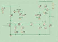
- Simple cascode for the 1st stage and subtracting the drain resistor value from the first RIAA resistor.
- Cascode + follower for the second in order to have better drive capability for the interconnects and lower output impendance.
Right ?
Adding a selector, a pot and a 3rd Cascode + Follower we have a very nice and compact (psu in a separate case) Preamplifier.
Right ?
Thank you for your replies
Kuei,
another setup could be
- Simple cascode for the 1st stage and subtracting the drain resistor value from the first RIAA resistor.
- Cascode + follower for the second in order to have better drive capability for the interconnects and lower output impendance.
Right ?
Adding a selector, a pot and a 3rd Cascode + Follower we have a very nice and compact (psu in a separate case) Preamplifier.
Right ?
Konniciwa,
Right.
You would need a different FET (IMHO) for the Linestage, lower transconductance and higher gate cutoff Voltage, a linestage with 36db gain re than a little excessive if you ask me....
Sayonara
Marinos said:another setup could be
- Simple cascode for the 1st stage and subtracting the drain resistor value from the first RIAA resistor.
- Cascode + follower for the second in order to have better drive capability for the interconnects and lower output impendance.
Right ?
Right.
Marinos said:Adding a selector, a pot and a 3rd Cascode + Follower we have a very nice and compact (psu in a separate case) Preamplifier.
Right ?
You would need a different FET (IMHO) for the Linestage, lower transconductance and higher gate cutoff Voltage, a linestage with 36db gain re than a little excessive if you ask me....
Sayonara
peranders said:Q1, Que? I'll gues the schematic is drawn wrong?
No, it has a purpose. Think about it.
") Otherwise, you can find
Otherwise, you can findit in an earlier thread, I just don't remember which one now.
The point is to try getting a constant supply current draw to
the input stage. It is just a dummy load intended to approximate
the inverse current draw of the input JFET.
I see now that Werner has edited and modified the schematic
slightly. It was perhaps a little bit more obvious in the earlier
one where V1 was a chain of RC links from the supply.
the input stage. It is just a dummy load intended to approximate
the inverse current draw of the input JFET.
I see now that Werner has edited and modified the schematic
slightly. It was perhaps a little bit more obvious in the earlier
one where V1 was a chain of RC links from the supply.
It is just a dummy load intended to approximate
Fascinating. Is the effect clearly audible? Why is C1 so small?
analog_sa said:
Fascinating. Is the effect clearly audible? Why is C1 so small?
Well, don't ask me, I haven't tried it. Achieving a constant current
draw should be beneficial for low level amps in general though.
As I said, there was a thread a while back discussing this
general principle and various ways to achieve it. As I remember
Jonathan Carr was quite enthusiastic about it, saying that the
major advantage was that one can get away with simpler
power supplies. He said that the choice of caps in the PSU
was not so important anymore.
I don't know about the C1 value. Maybe a typo? Werner?
This is not only relevant in audio. We used to have a company
called Facit here in Sweden which was quite big and advanced
in computer peripherals. In the 70's they tried to get an order
for printers to Pentagon. However, Pentagon did not accept the
printers after testing them, since they claimed it might be possible
to monitor the noise on the mains line and figure out what was
printed. These were dot matrix printers, so Facit made a special
military version of it, by simply adding an extra dummy print
head which was fed with the complementary data of the ordinary
one. The power demand thus summed to a near constant one.
Caps in the PSU
Bulk of discussion in this thread:
http://www.diyaudio.com/forums/showthread.php?postid=135006#post135006
With additional comments here:
http://www.diyaudio.com/forums/showthread.php?postid=193531#post193531
As always, YMMV.
regards, jonathan carr
Bulk of discussion in this thread:
http://www.diyaudio.com/forums/showthread.php?postid=135006#post135006
With additional comments here:
http://www.diyaudio.com/forums/showthread.php?postid=193531#post193531
As always, YMMV.
regards, jonathan carr
Hi all,
Werner explains this setup at his site
http://www.geocities.com/Hollywood/Hills/4133/design.html
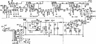
"........Since this scheme would result in a high power supply source impedance at low frequencies, the supplies load must be kept constant relative to the music signal. This is done hanging a source follower off the first stage's transistor which runs at the same current, but inverse in polarity. The follower can be filtered at its gate to restrict its operation to low frequencies only. ".
I think that the last sentence explains C1 operation.
Don't forget to give me some help about the "integrated preamp" (see previous post) guys.
Werner explains this setup at his site
http://www.geocities.com/Hollywood/Hills/4133/design.html
"........Since this scheme would result in a high power supply source impedance at low frequencies, the supplies load must be kept constant relative to the music signal. This is done hanging a source follower off the first stage's transistor which runs at the same current, but inverse in polarity. The follower can be filtered at its gate to restrict its operation to low frequencies only. ".
I think that the last sentence explains C1 operation.
Don't forget to give me some help about the "integrated preamp" (see previous post) guys.
No. The load at Q1's source is there to simply mirror the load at the front-end transistor's drain.
That 100nF and 750R at Q1 stems from part of the RIAA filter. We don't copy the whole RIAA as the bulk of the current flows in the 750/100nF pair anyway.
I make no claims as to the sonic benefits of this scheme. I expect it to depend heavily on the type of voltage supply anyhow. Some of you may want to try it, though.
Werner we have a discussion about the Jung regulator with extremely low output impedance (and the importance of it), your power supply seems to be very week since you need current compensation?? Isn't low impedance of the power source essential at all times?Werner said:I make no claims as to the sonic benefits of this scheme. I expect it to depend heavily on the type of voltage supply anyhow. Some of you may want to try it, though.
- Status
- This old topic is closed. If you want to reopen this topic, contact a moderator using the "Report Post" button.
- Home
- Source & Line
- Analogue Source
- Simple MM only RIAA preamp