I don't know, I haven't checked that.When floating, is there any voltage between chassis and mains ground prong before you attach mains gnd to chassis?
Before I do, let me introduce another line of thinking.
When I replace the SSHV with a 5k resistor I get a B+ of about 294V, and the unit appears to work very well. It's extremely quiet, I don't hear any hum at all. The music sounds good, too.
But, for the first 5 seconds or so after I power the unit on, the B+ is about 345V. There's no voltage drop across the resistor, I assume because the tubes haven't heated up and appear to be open.
So, with the SSHV in that position, if it saw both incoming and outgoing voltages of 345 and it was adjusted to produce a voltage of 300, would it be dumping a high amount of current (and therefore burning up R1)? Since the outgoing voltage is "stuck" at whatever the incoming voltage is for a few seconds, would that cause the SSHV to create a virtual short?
If this is the case, I guess the answer to my problem is a delayed start for the high voltage circuit.
Its good that the tube circuit itself is quiet anyway. The total current that the reg asks is always the same because its CCS asks for it anyway, the change is on the heat-sink during the time no share is taking place by the load. Some more thermal dump for a brief, not a problem for the currents and sinks involved. Is there a decoupling capacitor right across the reg's input? It could work chassis floating but because it circulates HV it is not a safe practice in the long term. The weird thing is that when having yin yang diodes it is insulated to chassis for 0,6V potential level. That is why I am asking if there is potential between chassis and mains earth reference.
Well I decided to test my theory. I put a switch on the input to the SSHV. I powered up the heaters and waited for the tubes to warm up, then I flipped my switch to start the SSHV. SPARKS! Big ones from around the Q1/Q2 area. And then R1 burned up. That's my final 220 resistor, I'll have to get more along with some low current fuses.
When I check voltage between mains earth and the chassis, it floats around between 0 and 100mV.
No decoupling capacitors. There aren't any components in my circuit that aren't in the schematic.
When I check voltage between mains earth and the chassis, it floats around between 0 and 100mV.
No decoupling capacitors. There aren't any components in my circuit that aren't in the schematic.
Don't know more, I can't think of other experiments. 6V6 & #26 line pre works with all regs, Maida, SSHV, SSHV2. Valve itch works with Maida, SSHV. Now in this build, either float it or use it without reg since its quiet anyway. Something's different that you may chance at eventually. But the tube riaa works and this is the main thing. What PSU and how is a peripheral.
Hi All,
Thanks for the PM's regarding the parts.
I now have most of them on the way, RIAA caps from Felipe, components & valves from Revmen.
I have also ordered a 260VAC mains transformer from jms on-line.
100 VA
I need to order the heater transformer, which would be more suitable?
Laminate or Toroidal, are there any advantages, do I need two?
Buy Chassis Mounting Transformers Clamp mount transformer,50VA 2x0-9V o/p RS 10-5941 online from RS for next day delivery.
Toroidal Transformer 230v Single Primary 50va 0 9v 0 9v
Chassis Transformer 230v 50va 9v+9v
The only part of the project that scares me is the point to point, this being my first time.
Does anyone have a series of close up photos of the P2P wiring, might help me and other along?
I have reread the thread, and there isn't a lot of photos to follow.
Really looking forward to the build.
Thanks for now
Ian
SPARKS!
......
When I check voltage between mains earth and the chassis, it floats around between 0 and 100mV.
Something dawned on me. Can there be some leakage from C12 or wrong polarity, so it brings DC elevation to PSU GND line? Wondering if having R7, R8, C12 say before the reg avoids some possible interference. Is there any possibility that the elevated heaters tube pair mix with the grounded heaters pair by mistake in the main phono build?
It's certainly possible I made a mistake in the audio circuit, and I can check that, but the problems still happen even when I substitute resistors for the audio circuit and run the power supply alone. When I ran it that way the audio circuit was, as far as I know, completely isolated from the chassis and everything else.Something dawned on me. Can there be some leakage from C12 or wrong polarity, so it brings DC elevation to PSU GND line? Wondering if having R7, R8, C12 say before the reg avoids some possible interference. Is there any possibility that the elevated heaters tube pair mix with the grounded heaters pair by mistake in the main phono build?
An externally hosted image should be here but it was not working when we last tested it.
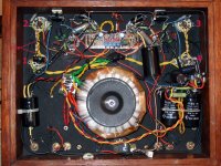
Deep deep joy. Salad is a god. After what must be nearly two years I have finally got round to switch on of my phono itch. Ill health has alas kept me away from this project except for very small and occasional forays into my workshop. I also found playing with high voltages whilst high as a kite on prescription drugs not a good idea. However finally we have lift off. A couple of component issues now resolved and she sounds great. I am currently trialling some hard hitting rock to see how it holds up to the more demanding end of my record collection.
As you can see I still need to box this thing but before I do I need to tweak.
First off earthing. I have a simple earth running through the whole thing and no shielding anywhere so some buzz but surprisingly not bad. Tips on earth improvements greatly accepted otherwise I shall read through the thread again.
Secondly I am using a 3k3 resistor at phono input following Salas recommendation for my Dynavector 10X4 (specs 2.5mv output, 47kohm load impedance). Can anyone tell me how this is calculated in case I ever change cartridges. Is it worth playing with this or other components in an effort to fine tune? It feels slightly harsh occasionally although even after an hour of playing I think it may be mellowing (or is that just psychological?)
Thirdly I worked to the very early designs as changing mid project would have been a level of complication beyond me at the time. Is there anything in the later mods that anyone would recommend as making a substantive difference.
Anyway many thanks to all for a great project that has helped keep my sanity over last two years.
Regards
Hi Revoli
Nice that you got around the build after time and hardship. Be well.
Regarding some buzz it looks like its a shielding priority on glance. No metal container for the pre, and transformers are near about. Shorten all wiring to tightest possible, narrowing the aerial loops.
Not sure if the signal input wiring is shielded from looking at the pic.
If not, that could help a bit for now. Also by looking back you can refer to Fran's GND wiring scheme.
If buzz receeds it can sound mellower even because it adds harmonics of its own, but having a Dyna 10X4 myself also in my stash I know it can show some bite occasionally.
Regarding the idea behind choosing its load resistor value, its about securing a times 10 higher resistor than the published internal resistance of the cart and trying a few higher values in steps up to 47K. 3K3 is the base and you can listen to some values above that. If the tonality won't be fully acceptable after that, try VTA tweaks, if still not content, some careful step by step addition of value to the 15nF RIAA HF capacitors can tilt the curve mellower. Say by using sub nF silver mica bypass caps to gradually go up to 16nF total.
Salas thanks for the tips. Will work through these. Boxes under construction then rebuild inside its new home. On previous form that should take about a year...... I also have a bunch of different valves to test in it as they are reasonably cheap and it seemed a good idea at the time. Great project, great sound. Another step on the ladder to reach sound nirvana.
Earthing
I have read with intrest the posts from Fran and Salas on earthing this. Think I know what I am doing but before commiting wire to wire could someone just confirm my queries. I have taken Frans drawing and scribbled on it as I am fundamentally lazy. On my notes page attached:
1. Am I right in how I wire the capacitors at the input jacks with 0.01uF caps?
2. I cannot read Frans writing circled in pink. What does it say?
3. At top right in red am I right, 0.01uF caps, 15R 5W resistor and a couple of inverted UF4007 diodes and no other direct connection to chassis for bus bar?
Is it worth putting shielded cable anywhere else? I also have an amount of expensive silver wiring I could use in here Its quite thick but is it worth bunging in on signal path - shielding it first?
My final build will be two box so a sort of hybrid star/bus bar earth. I am assuming I can take the earth straight back from the phono box to the PSU box. Anything clever I should do between the two to stop stray signals creeping into the Phono bus bar? I assume I can replicate what is proposed for the bus bar connection in the diagram (circled in green) and connect phono earth at point E. Bit nervous on that as want to be sure earth is safe so please confirm someone!
Is it worth upgrading the C2 (47nF), C3(15nF), and C4 (47nF - 0.1uF in mine currently) (in Salas Valve Itch Rev 1.1) to paper in oil russian caps if I can get them? All after eliminating buzz of course! Thanks all.
Attachments
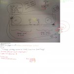
Not to answer on Fran's account on details until he will be reading your questions at a point, at least I think he notes encircled in pink from left to right ''elevated heaters to 1/2 B+'' and ''grounded heaters to PSU GND point''.
The 10nF input RCA ring local to chassis caps are meaningful in a metal environment, i.e. not in yours yet. They are to ground RF before it enters the circuits traveling through shared ''clean'' signal ground paths to 0V.
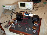
There are many ways someone can wire such a build successfully, I recommend you try shielded coax (the rather thin variety) for your signal runs and evaluate result before you attempt drastic changes. Its we identify the sources of slight buzzes first or we guess by eliminating possibilities. Better is we have a very silent FFT set up and we loop the phono as we watch harmonic noise tweaking by educated trial, but I am aware that the majority of builders in this thread aren't such equipped and familiar yet.
I had used with success one end (towards bus) shorted coax for GND returns you ask about, because they had to run around a 250VA toroid in a KT88 20W design of mine. Its noise floor attached, a fully AC heated 3 stage amp that was. See also how the short bus bar and shielded returns have been arranged for ideas. Grounded copper shield around Tx does help also. Save your silver IMHO.
To guess about Riaa caps upgrade worth to Russian PIO, you should give more info on brand and type you currently employ.
The 10nF input RCA ring local to chassis caps are meaningful in a metal environment, i.e. not in yours yet. They are to ground RF before it enters the circuits traveling through shared ''clean'' signal ground paths to 0V.
There are many ways someone can wire such a build successfully, I recommend you try shielded coax (the rather thin variety) for your signal runs and evaluate result before you attempt drastic changes. Its we identify the sources of slight buzzes first or we guess by eliminating possibilities. Better is we have a very silent FFT set up and we loop the phono as we watch harmonic noise tweaking by educated trial, but I am aware that the majority of builders in this thread aren't such equipped and familiar yet.
I had used with success one end (towards bus) shorted coax for GND returns you ask about, because they had to run around a 250VA toroid in a KT88 20W design of mine. Its noise floor attached, a fully AC heated 3 stage amp that was. See also how the short bus bar and shielded returns have been arranged for ideas. Grounded copper shield around Tx does help also. Save your silver IMHO.
To guess about Riaa caps upgrade worth to Russian PIO, you should give more info on brand and type you currently employ.
Attachments
Hi All,
Sorry to quote myself again, I have now bought received all the parts except the heater transformers, can you advise me on the most suitable please?
Sorry to quote myself again, I have now bought received all the parts except the heater transformers, can you advise me on the most suitable please?
Hi All,
Thanks for the PM's regarding the parts.
I now have most of them on the way, RIAA caps from Felipe, components & valves from Revmen.
I have also ordered a 260VAC mains transformer from jms on-line.
100 VA
I need to order the heater transformer, which would be more suitable?
Laminate or Toroidal, are there any advantages, do I need two?
Buy Chassis Mounting Transformers Clamp mount transformer,50VA 2x0-9V o/p RS 10-5941 online from RS for next day delivery.
Toroidal Transformer 230v Single Primary 50va 0 9v 0 9v
Chassis Transformer 230v 50va 9v+9v
I purchased the JMS 260V 100VA transformer, it has no centre tap, is that a problem for this build?
Would I be better buying tag strips, tag boards or fanning strips to ease my first point to point?
Many Thanks
Ian
Not to answer on Fran's account on details until he will be reading your questions at a point, at least I think he notes encircled in pink from left to right ''elevated heaters to 1/2 B+'' and ''grounded heaters to PSU GND point''.
The 10nF input RCA ring local to chassis caps are meaningful in a metal environment, i.e. not in yours yet. They are to ground RF before it enters the circuits traveling through shared ''clean'' signal ground paths to 0V.
There are many ways someone can wire such a build successfully, I recommend you try shielded coax (the rather thin variety) for your signal runs and evaluate result before you attempt drastic changes. Its we identify the sources of slight buzzes first or we guess by eliminating possibilities. Better is we have a very silent FFT set up and we loop the phono as we watch harmonic noise tweaking by educated trial, but I am aware that the majority of builders in this thread aren't such equipped and familiar yet.
I had used with success one end (towards bus) shorted coax for GND returns you ask about, because they had to run around a 250VA toroid in a KT88 20W design of mine. Its noise floor attached, a fully AC heated 3 stage amp that was. See also how the short bus bar and shielded returns have been arranged for ideas. Grounded copper shield around Tx does help also. Save your silver IMHO.
To guess about Riaa caps upgrade worth to Russian PIO, you should give more info on brand and type you currently employ.
Very nice pics Salas, for sure sounds very good
")
Hi All,
I am just about to order the remaining parts, and would really appreciate a few answers.
I have a Toroidal 120VA 2x18V sitting here unused, can I use this for the heaters?
Will the 10K trimmer & 470 reduce the output enough? Or am I stressing the LM317 to much?
Would save me a lot of money if i can use it.
What would be the value 10W resistor dummy load for setting the SSHV2, ie the mA target circuit's nominal consumption?
Thanks in advance.
Ian
An externally hosted image should be here but it was not working when we last tested it.
An externally hosted image should be here but it was not working when we last tested it.
PSU box nearly done. Just about to order parts for cable between psu box and phono. It strikes me that I can get away with 5 core cable as per labels 1 to 5 on attached but v1.1 shows 7 (letters A to G). What is best for this please.
- Home
- Source & Line
- Analogue Source
- Valve Itch phono