Understood, but the 2 C/W is for a downward facing orientation (flat side on the top). If I set it on its end, convection will be more efficient. Still, though, I don't know how much more efficient, so it's probably best not to guess.
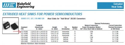
I reckon I don't understand how to determine how much heatsink is needed. I was thinking in terms of the 11W dissipation at dT=60 for natural convection, which I suppose would mean ~6.4 W at dT=35 (60C-25C). And I suppose that allows us to dissipate 21 mA at 300V, or have I got that wrong?
How much spare current would we expect in this circuit? Would it be higher or lower than 20 mA?
When you got over 40C in a valve circuit box such a sink can rise up to 75C. 300Vx0.02A= 6W and a 2C/W will get you to 55C in a hotter day which is much more agreeable. When having 55C on a sink its not difficult to have 100C plus on the silicon junction to have a picture. Don't skimp on sink area, this is constant current giving it no cooling off cycle %. 20mA spare is the recommended compromise. If you give it 30mA the reg's spec gets better and so it goes. Measure 60C max on your sink for max spare after half an hour in real box is a safe rule of thumb.
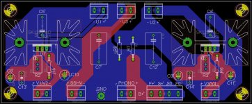
Those MKP caps are in good 1% RIAA tolerance to make a build care free and economical. It was not easy to find 1% in those voltages and it was a must of getting many and having an LCR meter for other brands and types in sane prices. They aren't something special to must substitute an already installed trimmed array of other caps was the deal, or am I wrong in that assumption?
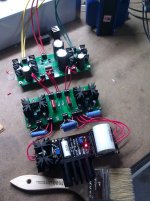
With the receipt of the SSHV2 board a few weeks ago, I began assembly of my power supply. Tonight I connected all of the pieces and tested it. So far it's perfect. Rock solid voltages at all 3 outputs. The SSHV2 is fantastic. The voltage across the TP points hasn't changed even 0.1 mV since I set it. The B+ voltage hasn't drifted at all, either. Both of the heater voltages are exactly where I set them. This is great.
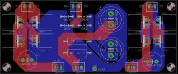
I got some help on the design of my PCBs from a local EE who I met through AudioKarma. He gave me a lot of good tips, particularly about using lots of copper. I have a few changes I want to make if I ever make another set, but they seem to be working very well so far. I had a few of each made through Silver Circuits, and the build quality is above satisfactory for the price I paid.
I had a custom power transformer made by Edcor. It saves space and looks nice. I've got my chassis cut out and ready to wire. That will be my project this weekend. If everything goes according to plan, I will have music on Sunday.
Attachments


Well..... I've got the circuit assembled, though I haven't physically put the whole unit together. But it's functional so I can test it.
It doesn't sound that good. The high end is very muted. I've attached a couple of samples. One is from my valve itch, the other is using a Musical Fidelity V-LPS. The turntable is a Dual 1229 (that needs a new idler) with a Shure V-15 III cart with a JICO SAS stylus.
What might be the reason for this? What are some things I can try to fix the lack of clarity?
There's also some hum that I'll have to chase down. I think I've got something grounded wrong.
Attachments
- Home
- Source & Line
- Analogue Source
- Valve Itch phono