The little I know of MM carts say they need to be tuned in with a small amount of pF. A tranny would be devestating in that logic. Thanks for working the link Dirkwright!
There's usually more than enough capacitance in the cable.
It would take a very special transformer to work with an MM. You have a source impedance that varies with frequency and gets quite high in the treble, so you can't optimize the load for the secondary. The leakage inductance and parasitic capacitances will also cause a severe HF rolloff because of the high source Z.
Fortunately, the levels are high enough that you can achieve a high CMR balanced in without transformers.
Fortunately, the levels are high enough that you can achieve a high CMR balanced in without transformers.
It would take a very special transformer to work with an MM. You have a source impedance that varies with frequency and gets quite high in the treble, so you can't optimize the load for the secondary. The leakage inductance and parasitic capacitances will also cause a severe HF rolloff because of the high source Z.
Fortunately, the levels are high enough that you can achieve a high CMR balanced in without transformers.
Yeah, that's basically my conclusion also.
Hi,
Thanks for looking into it.
Is this doable with the low 24V PS that feeds the 4 triodes of the ECC88 stage as it is now or do I need a raw supply higher voltage for that?
I'm lost about the second part of your observation though. Does that refer to the first stage of the itch being fed from a dedicated 320V supply and ditto CCS?
I'd agree that the phono preamp would benefit from a dedicated supply on a pro stage basis, just not sure if that is what you had in mind.
Cheers,")
P.S. Went to the bedroom on my knees laughing a few nights ago after reading you last PM....
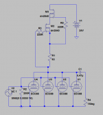
I looked into it a bit and I think it could be running just at 10mS in total as it is, with such a Jfet CCS about 6mA is to be expected. So something like 1.5mA per triode. Half the transconductance of a 5mA 2SK170GR for the whole composite pre pre in other words. 5mA per triode can boost to 20mS for 3dB better SNR. DN2540 can provide and its actually a good CCS down to a 20-25mA minimum level. Two in self biased cascode is even better high Z vs. Freq.
The Itch itself could push its input transconductance a bit also if there is raw DC spare for 320V B+ and R3 became 330 Ohm in combination. Little thing, but it could be better driving its EQ network in the highs. To maybe avoid double up experiments and more Miller for Stajo.
Thanks for looking into it.
Is this doable with the low 24V PS that feeds the 4 triodes of the ECC88 stage as it is now or do I need a raw supply higher voltage for that?
I'm lost about the second part of your observation though. Does that refer to the first stage of the itch being fed from a dedicated 320V supply and ditto CCS?
I'd agree that the phono preamp would benefit from a dedicated supply on a pro stage basis, just not sure if that is what you had in mind.
Cheers,
P.S. Went to the bedroom on my knees laughing a few nights ago after reading you last PM....
Those are depletion mode NMOSFETs work as -2VGS(OFF) JFETs. They should work stably when you got VGS*2 to spare across them.
The second part is just a suggestion to Stajo for using a little more B+ and a smaller current setting resistor in the μ Follower to push the 6N2PEV a bit in the circuit as is.
Just bcs he was thinking of doubling up on input triodes. He could achieve almost the same effect with a single. He could also use 1N4148 instead of an IR LED to achieve even more current and gm although few mV of grid current effect over the 47K may start to appear.
Hi,
O.K. I think it is just about doable with only just a few volts left to spare.
The important thing is that the composite block of triodes is kept into the starved voltage zone of roughly 12VDC plate voltage.
As for the second part, personally I would not // the triodes of the input section as it will also require the RIAA values to be recalculated.
All in all I feel that there's more to lose than to win by doing so but that's just my opinion.
May as well opt for single triodes in that case.
I also recall you mentioning that the channel separation of the Itch is maybe not so great as it is due to the two channels sharing one envelope.
However, as the 6N2P has an internal shield (just like a ECC88) this should not be affected provided this shield is grounded. Which it is as I understand it.
IOW, a channel separation of 30 to 35dB which is in the range of what most MCs have on offer anyhow should easily be feasible. Unless compromised by careless layout.
Cheers,
Last edited:
Hi,
O.K. I think it is just about doable with only just a few volts left to spare.
The important thing is that the composite block of triodes is kept into the starved voltage zone of roughly 12VDC plate voltage.
Cheers,
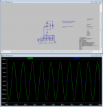
Should go up around 15-16V plate with 5mA per ECC88 if the sim model is any good. Is that a problem? Looks normal it should bias up a bit with more current used.
Hi,
That's magnificent.
It could even be integrated with the Itch if we steel the raw voltage somewhere from the B+.
I'm actually very happy as it provides a long term solution since the J-FETs in TO92 package are being slowly phased out, etc. Plus it quite likely outperforms the J-Fet current source anyway.
Great, thanks a bunch for simming this.
Ciao,
Hi,
Not if the 7824 can be kept in place as I don't think the MPSA14A (cap mult.) can have much more than on its input(need to check this)
The load line of the tubes should still be O.K. though. All in all I don't think the few volts more will affect the input impedance in any appreciable way.
At first glance: should work fine.
(If not, I don't understand anything anymore. Won't be a first. )
Ciao,
P.S. Owe you a fine Belgian beer or two.
Should go up around 15-16V plate with 5mA per ECC88 if the sim model is any good. Is that a problem? Looks normal it should bias up a bit with more current used.
Not if the 7824 can be kept in place as I don't think the MPSA14A (cap mult.) can have much more than on its input(need to check this)
The load line of the tubes should still be O.K. though. All in all I don't think the few volts more will affect the input impedance in any appreciable way.
At first glance: should work fine.
(If not, I don't understand anything anymore. Won't be a first.
)Ciao,
P.S. Owe you a fine Belgian beer or two.
Hi,
That's magnificent.
It could even be integrated with the Itch if we steel the raw voltage somewhere from the B+.
I'm actually very happy as it provides a long term solution since the J-FETs in TO92 package are being slowly phased out, etc. Plus it quite likely outperforms the J-Fet current source anyway.
Great, thanks a bunch for simming this.
Ciao,
I wonder at what plate current and gm that composite will start oscillating though.
Hi,
Not if the 7824 can be kept in place as I don't think the MPSA14A (cap mult.) can have much more than on its input(need to check this)
The load line of the tubes should still be O.K. though. All in all I don't think the few volts more will affect the input impedance in any appreciable way.
At first glance: should work fine.
(If not, I don't understand anything anymore. Won't be a first.
Ciao,
P.S. Owe you a fine Belgian beer or two.
Piraat high octane one please. Promise I won't shake it before I drink it.
Hi,
Sssshhhtttt.... nah, it didn't oscillate before.
You need to tell them tubies they're in the LF zone now and all will go well.
You shake it, you won't drink it.
Ciao,
I wonder at what plate current and gm that composite will start oscillating though.
Sssshhhtttt.... nah, it didn't oscillate before.
You need to tell them tubies they're in the LF zone now and all will go well.
Piraat high octane one please. Promise I won't shake it before I drink it.
You shake it, you won't drink it.
Ciao,
Sssshhhtttt.... nah, it didn't oscillate before.
You need to tell them tubies they're in the LF zone now and all will go well.
Ciao,
Will provide double the gm it used to have in this current now. Hope it stays put. After you will set 20mA with a VR1 (each DMOS sample has variation) better substitute a good fixed resistor for permanent reliability and better current noise.
P.S. If the combo can use even more current without instability and the plate voltage is still good for the chosen PSU at a yet valid curves point, test by lowering VR1 for more Ip & gm before fixing it for good. Max gm allowable is of course welcome for the low noise head amp purpose of that circuit. It will not go under 1nVrtHz easily and 1/F should be rather boiling when fed from such low source resistance, but anyway, good enough for using common tubes. Can select samples.
Neat. 8 tightly matched E88CC halves is not low hanging fruit anymore. 6N23P?
Anything clone should do. Those are double elements bottles as you say so four select ones for gm and noise can do two channels. This is alternative to an LMC SUT but not exactly the noise, not the anti-hum balanced primary, polarity inverting. Cheaper, 30dB, any input load you choose, no magnetic circuit bandwidth or response linearity limitations on the other hand.
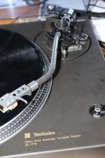
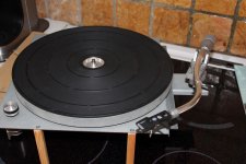
No I have not. Just mailed the shop cause I have no send reciept either. For starter I think it will be this Technics one. Then I have some TD150 and L75s to play around with.
If one is seroius about channel separation there can be doable with double 6N2PEV and 2+2 6J5.
What arm types (weight etc) is recommended?
Edit, got an answer "Går idag /Lasse" (Ships today)
If one is seroius about channel separation there can be doable with double 6N2PEV and 2+2 6J5.
What arm types (weight etc) is recommended?
Edit, got an answer "Går idag /Lasse" (Ships today)
Attachments
Last edited:
- Home
- Source & Line
- Analogue Source
- Valve Itch phono