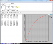
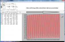
By setting delay and measuring time you can "zoom" into the startup phase to look for if the caps are sucking energy from the transformer that starts ringings.
I dont see any such tendencies here. Of course this has to do with many factors like the speed and size of caps etc. Inductors in the filter chain can also start interfere with caps and trannys in a bad way to show this edgy behaviour under startup.
Snubbers can be good but its very hard to test them out. There is no "one size fits all" value there. So if you cant test them out leave them out. They can certainly cause more harm then good.
Attachments
I ont' understand why the voltage at the load varies depending the ms and the delay?
I presume that you by "voltage at the load" meen V(I1) in this case. It shows minimum value and maximum value over the voltage over load (I1). Third column "Diff" is "Max minus Min voltage over load".
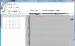
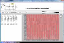
If you set the measurment with a delay long enough so caps has charged and startup phase is over then "Diff" is "ripple under run".
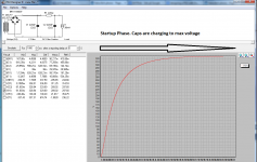
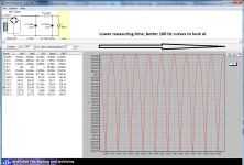
If you set it with no delay "Diff" is "Zero to Max voltage" which is not very interesting if youre looking for ripple.
Does that make sense?
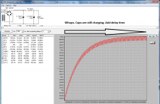
I made some pix for you. Maybe those say more then words. Look at measured time and delay at every picture and how the curves and measures change.
Its all the same circuit, just different measuring time and delay.
Its all the same circuit, just different measuring time and delay.
Attachments
Salas what's the max. ripple allowable for SSHV2?
?
10nF between signal an ground to avoid antenna efect caused by the cables.
Maybe between RCA ring and chassis?
")
Ricardo Salas is right
Yes, of course.... I remember perfectly, but I got the idea... You used 10nF without passband penalties.... Cool
Now you removed the cap because you improved matters all around.... must do an itch soon.
Are you using a SUT or a solid state prepreamp ?
Yes, of course.... I remember perfectly, but I got the idea... You used 10nF without passband penalties.... Cool
Now you removed the cap because you improved matters all around.... must do an itch soon.
Are you using a SUT or a solid state prepreamp ?
Both: Partridge 977 & Masterpiece by Joachim Gerard
Not more than a Volt would be fine.
It's probably already been said (I'm not going to read through 101 replies) but excellent circuit, but the 6SN7 (equivalent) works better above about 7mA (see it's curves). Also, if you want it to be compatible with moving metal cartridges as well, you'd want to have a variable cap from the input to gnd across the 47K so you can load a given cartridge properly. This can make a big difference in the high frequency response.The ''Valve Itch'' circuit.
Edit: Later updated schematic Rev1.1 http://www.diyaudio.com/forums/analogue-source/140635-valve-itch-phono-40.html#post2661096
On the power supply, I always DC bias my heaters such that I don't exceed the heater to cathode spec, which usually means up around 100V. This is often overlooked and is especially important when using followers or any variation of a cascode type topology, where the upper tube will have a substantially elevated cathode voltage.
There is elevation for the upper tubes. A line from a B+ divider tap to V3,4 heaters in the PSU part of the linked schematics you quoted.
As for MM loading, as there is some Miller adding to cable pF already, another interesting method is a variable resistance load. Its influential in tuning.
As for MM loading, as there is some Miller adding to cable pF already, another interesting method is a variable resistance load. Its influential in tuning.
Yes, I mis-read how you were doing the heater supplies. I've been told (by the hardcores in our local audiophile club) that many MM cartridges are very sensitive to loading R and C, and should be fine tuned with a test record, or the results, even with an otherwise great preamp will be random. It appears that this is often overlooked or only approximately adjusted. I suspect that moving coil cartridges are much less sensitive to this, which may be the main reason why people think they sound better (?).There is elevation for the upper tubes. A line from a B+ divider tap to V3,4 heaters in the PSU part of the linked schematics you quoted.
As for MM loading, as there is some Miller adding to cable pF already, another interesting method is a variable resistance load. Its influential in tuning.
- Home
- Source & Line
- Analogue Source
- Valve Itch phono