How to Test MOSFET Transistors | eHow.com
Q2 is depletion mode N type.
Q2 is depletion mode N type.
Normally they need about 50-60R including 10R TP resistor for about 30mA if they are at the usual ~1.5V low point at that current region when working in that CCS. TP testing for Ohm also shows very near to 10 Ohm when all is installed. Now you took it off what is the ohmic reading on TP?
Normally they need about 50-60R including 10R TP resistor for about 30mA if they are at the usual ~1.5V low point at that current region when working in that CCS. TP testing for Ohm also shows very near to 10 Ohm when all is installed. Now you took it off what is the ohmic reading on TP?
Still 7R4
R5 should be 10R if you will lift one pin and measure it. It should be ~9.45R on TP for 47//47R instead of trimmer. See about changing the Zeners, about surely having a Vout that allows at least 10V difference to Vin, and that also Q1 shows ~1-1.5V Vgs which you can also measure as Vds Q2 when you have the power on.
Could it have been some form of oscillation with the previous SUTs even? Does the new OK situation reflect to an uplift in perceived sound quality?
P.S. Try 18K-22K, it also gave me good square waves with the 977.
Hi Salas
Thanks for your thoughts on loading resistor values. I have been listening to the phono a lot over the last two days, I still percieve a little more gain in one channel than the other.
There was/is no evidence of oscillation on the scope with either of the SUT's. However the original setup with the Sowter SUT's inside the phono enclosure was very prone to RF interference and mains bourne spikes, so there could have been something.
I have the new 977's in an external die cast aluminium box, but of course now there is another set of cables and phono sockets inbetween the cart and the input grids. The sound is certainly top class, excellent bass resolution and very quiet with zero hum.
Now I know how it sounds I would like to rebuld the whole thing in a more compact enclosure. What would be great if someone on this forum could lay it out on a PCB and make some available as a group buy. Unfortunately I only have rudimentary PCB skills. I'm trying to learn Eagle, but I don't think I'm up to laying out a phono stage just yet!
")
Hi Salas
Thanks for your thoughts on loading resistor values. I have been listening to the phono a lot over the last two days, I still percieve a little more gain in one channel than the other.
Could you measure the difference in dB @ 1kHz with and without the SUTs? Use 50 Ohm generator when with the SUTs. Swap channels since the SUTs are external, If the gain difference swaps with channels its the SUTs difference. If you can not find enough difference by measuring, then try antiskating with a test LP in case its source related.
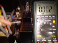
R5 is 10R measured lifting one pin, soldered again R5, the two zeners were burned measured continuity both poles so I changed for two new ones now TP measures 10R but current measured TP it's too low see pic.
Check and note things one after the other as in #1034. Have you had that reg used before in another situation? Did it ever smoke?
- Home
- Source & Line
- Analogue Source
- Valve Itch phono