Hi revoli
I followed your build, since first looking at Sala's 'Itch'.
SOUPER-N I C E job on it...
...great copper shielding on the oh so beautifully dove-tailed woodwork.
Pleased you like the sound as well.
Keep the listening reports coming.
Just out of interest...
...what old phono-stage is now gathering dust in the shed ?
Top design Salas.
Cheers
Si.
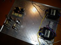
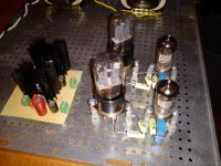
Herewith the final production photos. Taken a little while but works great.
Very neat looking and compact build, well done! Is that a copper top plate?
Looks like you used the same heatsinks on the LM317's as I did. I found they got a bit too hot for comfort inside the closed case in my build, so I doubled the size of them by making a small extension plate.
Strange problem with valve itch
I noticed that I am getting noticably more gain from the left channel than from the right channel. The problem is coming from the first 6N2P stage.
From my stock I have selected the valves for examples with near perfect balance between the two triodes in each envelope.
In circuit I measure excatly the same voltage drop over the 47 ohm and the 82K ohm resistors in the first stage for both channels. All the other DC voltages are correct and match to within 0.5 volts. Yet if I inject a signal on both the left and right inputs and check with the scope I have more voltage swing on the left channel than the right, about 20% difference between the two.
If I measure the AC signal at the input to the RIAA stage, the junction of the 50K resistor and the 47nf capacitor, they are different by 20%.
If I go further back in the circuit and measure the AC signal on the anodes of the V1 (pins 1 and 6) I have 10v p-p on the left channel and 8v p-p on the right channel.
I have checked the output voltage from the step up transformers and that is identical. So what could be going on here, anyone got any ideas? Some sort of RF oscillation perhaps? Although I can see no evidence of that on the scope.
I have checked the circuit (several times) and all the resistor values are correct.
I'm stumped! Other than oscillation in one channel I can see no reason for the AC voltage difference. The only other thing is some mismatch in the 0.1uf feedback capacitors, C1.
Im in need some new ideas.
Thanks
Martin
Update Starnge problem with valve itch
OK I have done a little bit more investigation and I have traced the signal imbalance right back to the grid of the input valve.
If I inject a signal into the MC step up transformer with the phono stage switched off and I measure the AC signal voltage at the grid of the input valve across the grid/load resistor the left and right channel signal voltages are identical.
If I power on the phono stage as the input valve starts to conduct the AC signal voltage at the grid drops significantly on both grids as expected, but the input signals become imbalanced by roughly the 20% I measured earlier on the output stage and at other points in the circuit.
If I measure the grid voltage I get different readings at the the left and right grid pins. -0.038 volts on the left pin and -0.024 volts on the right pin. I have an 8K2 and 47K grid resistor in parallel (6K98)to give a reflected load to the MC cartridge of 70 ohms through the 10:1 step up transformers. So there is a very tiny amount of negative grid current flowing.
I have tried several valves in the input position and the grid voltage is always greater on the left channel and subsequently it's always the left channel with the lower signal.
I don't really understand what's happening here and how to fix it other than putting a blocking capacitor between the secondary of the MC step up transformer and the grid of the input valve.
I still need some more ideas
Thanks
Martin
It was quite easy to channel match on the two originals by just swapping a couple of input tubes. Not seen anything like 20% in the first place though. Are the tubes the low grid leakage EV types? If you stick an LED between each of their cathodes and ground do they change their discrepancy at all?
Are the tubes the low grid leakage EV types? If you stick an LED between each of their cathodes and ground do they change their discrepancy at all?
Hi Salas
I have tried many different tubes today, both the EV and E types, the problem is still the same. I've not tried any led's in the cathodes as yet, no more time left today, I've been on it all day. I suspect it's something to do with the Sowter step transformers, but I don't know why. When I get some more time I am going to try with the step ups out of circuit.
I can't understand why it's always the same channel despite changing the tubes about.
Some bias to the SUTs maybe, and different saturation? What if you don't load them so low? Haven't gone lower than 18K to tell.
I tried them at 47K load today and it's the same imbalance.
I'm not liking the idea of a blocking capacitor between the SUT's and the grids, but I am going to try it to eliminate the SUT's. I'm not sure about saturation of the SUT's, any grid current at -0.038 volts is going to be extremely small.
Swap then for channels first, to see if its related.
Yes, good idea, I'll try that first.
Some bias to the SUTs maybe, and different saturation?
Actually you are quite correct. The problem is different saturation of the SUT's.
I removed the SUT's from the inputs and measured the voltage on the input grids with the 47K grid resistors in place, I found that the grid voltage rises to minus 0.24 volts on both grids without the SUT's. So there is more negative grid current flowing than I thought.
Without the SUT's in circuit the gain is identical on both channels. I now realise I cannot use the Sowter SUT's I have without a blocking capacitor.
These are the transformers I'm using:
Sowter Type 6496 Phono Cartridge Transformer
I guess they don't like any DC on the secondary windings
I am collecting a pair of Partridge 977 6:1 SUT's at the weekend, which I'm hoping will fare a little better, providing the 6:1 step up ratio will be enough for the MC cartridge I'm using.
Ortofon MC25FL (Output voltage at 1kHz, 5cm/sec=500µV)
That cart you got has very good SNR and nice sound. Partridge 1:6 is one used by Fran in Ireland, he did not have problems. I had put the same in a simplistic MM to convert to MC input also, and I had seen best square waves when its secondary was loaded around 18K if I remember exactly. Check with square waves, its a good test. Lets see if they will do OK in yours too then, good luck.

- Home
- Source & Line
- Analogue Source
- Valve Itch phono