If you attach to chassis only from where the GND wires of the regulator meet the load what happens? R1 burning means there is a direct current loop created from rectification to earth.
The same thing. R1 burns up. I've tried connecting ground to chassis:
-around the rectifiers via a ground plane that connects the (-) of C1, C3, R4, etc.
-around the regulators via a ground plane that connects S0, F0, the 0 input to the SSHV board, the ground from the audio circuit, and the (-) side of the V1/V2 heaters.
-presumably through the chassis ground connection from the turntable. In this case the circuit inside my chassis was floating and the unit would power up and appear to work correctly, but when I connected the turntable R1 burned up.
P.S. You got some custom PSU boards created, yes? Is there any differentiation taking place there considering earth?
I don't understand what you mean by "differentiation." There are 3 pairs of wires connecting the AC and DC boards. One pair across C1/C5, one across C2/C6, one across R4/C7.
The low sides of C1, C5, C4, R4, C7, B+, and the SSHV board are all tied together. This is how I interpreted the schematic. Was that incorrect?
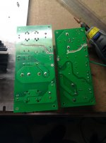
I've attached my Eagle files if you'd like to take a look at the two boards. Maybe you can see the answer to your question or a problem I haven't been able to identify.
Attachments

Just a proposition that may talk back to us, nothing sure when I don't have actual the build in front of me. V1, V2 h may float for now. In case of slight buzz due to this we will talk. Lets see if the main problem stops first.
I separated the V1/V2 heater ground planes from the B+ ground planes, essentially doing the mod that you suggested. No difference, R1 burned up.
This was a fun use of my Dremel tool, though.
Attachments
But not connected to chassis from there, only at the first rectification capacitor's (-)?
What are the differences if you compare the way that build is connected? (#post210).
What are the differences if you compare the way that build is connected? (#post210).
Currently it's connected to the chassis at that point through the yin-yang diodes. Previously it was connected by the (-) side of C3, but I moved it over to this spot on your suggestion. Since both of these points are at the same potential, I don't see what difference it makes.
I disconnected the SSHV Regulator from the circuit entirely and connected B+ to C7 directly. R1 does not burn up and B+ holds at ~350V. So it looks like the problem has something to do with the SSHV board.
What would cause the SSHV to draw so much current?
Is it possible for any of the SSHV components (Q1?) to fail to a short condition?
Is it possible the R4 current adjustment is too high? I set it when the whole circuit was floating, would connecting the ground to chassis change the potential seen by Q2 from R4?
I am looking at physical points of grounding due to there is the sense circuit in the reg and because of the board plane and the size of the general build it can be not seeing a defined ground node to sense and it may gets confused. So I was wondering now that the heating and B+ grounds got separate at the planes if the Gnd point could be revised. Also if the sense and force are shorted locally at the reg and it becomes a 2 wire out to load, will it change behavior? Are there force and sense connections running through the custom boards as vias? Is the sensing in anyway elaborately made?
Also if the sense and force are shorted locally at the reg and it becomes a 2 wire out to load, will it change behavior? Are there force and sense connections running through the custom boards as vias? Is the sensing in anyway elaborately made?
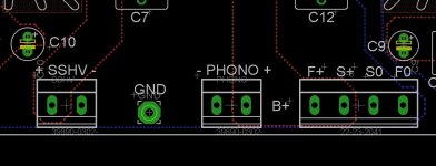
It is very non-elaborate. See the attached picture from Eagle.
The SSHV +/- connectors go to the input of the SSHV board.
The GND pad is where it is currently connected to the chassis, although previously it was from the other board. It behaves the same in either case.
The PHONO +/- connectors go to the audio circuit.
The F S +/0 connectors go to the corresponding connectors on the SSHV board.
SSHV-, GND, PHONO-, S0, and F0 are all connected through a single plane on the bottom of the board (blue outline).
PHONO+, S+, and F+ are connected through a single plane on the top of the board (red outline).
The SSHV board is less than an inch away from these connectors.
Just now I tried turning the current adjustment way down on the SSHV and started it up. Same result: burnt R1.
Attachments
Last edited:
Something's fishy when the reg is routed through the PSU sub-board, oscillation maybe. It could be setting off and killing R1 like a fuse the moment it refers gnd to chassis. There is a hint when everything is OK before a bigger low impedance ground plane I.e. the chassis gets involved. The hint is change in ground impedance and sensing to the reg since when with no reg no R1 kill i.e no bad ground per se, no kill when reg floats in respect to chassis as well. This is our X factor VS previous builds, unknown impedance gnd nodes on new go-between boards, sensing off target nodes. You terminate sense at PSU board not at load in that picture, that's new. So lets investigate. Just short F+,S+ & F0,S0 at SSHV2 output connector, make it effectively a 2 wire classic non Kelvin output and connect directly to phono B+, GND. Use twisted pair, short, no sub boards involved in that feed. Lets see.
The wires that connect the PSU board to the SSHV board are about 2" long at the most. I am willing to try your suggestion, but I want to make sure you really think there's an actual possibility that it could be any different than shorting F0/S0 and F+/S+ at the SSHV terminals instead of at the PSU board. I just don't want to replace that resistor again if there's no point in doing it.
OK, good idea.
Instead of putting the resistor back on the PCB, I attached leads so that I can connect things to a breadboard.
I didn't have any 100mA fuses so I put a 1A fuse in series with the resistor. This is too big, I'll have to get some smaller value ones later today.
I made the change you suggested, shorting F0 to S0 and F+ to S+ at the SSHV terminal blocks instead of at the PS PCB terminal blocks. R1 burned up (but at least I can replace it by putting it into a breadboard now).
- Home
- Source & Line
- Analogue Source
- Valve Itch phono