A group of friends and I are building these for ourselves. We bought our parts together, which saved some money. Instead of etching all of the boards, I thought it might be cost effective if we had PCBs made for the power supply.
Attached is my first crack at an Eagle PCB project. I've never used Eagle before, and I've never designed a PCB before, so it might be very bad. I'm hoping that someone more knowledgeable than I will have the time and inclination to look over my work to see if it's any good.
Basically I just split the power supply into 2 boards, the AC section the DC section. I built the SSHV into the DC power board, I didn't see any reason not to. Both boards are the maximum size allowed by the free version of Eagle. Both boards are double-sided, I didn't see a way to do them single-sided. All of the traces are 70 mil, which I understand is appropriate for the ~3.5 A sections.
I would really appreciate any feedback anyone has. It won't hurt my feelings if you say it's very bad.")
And of course if this work is of value I have no trouble sharing it with everyone. I plan to order PCBs for me and my friends as soon as possible, so if anyone else is interested in getting some I'd be happy to add a few units to the order for you and ship them to you when they're finished.
Attached is my first crack at an Eagle PCB project. I've never used Eagle before, and I've never designed a PCB before, so it might be very bad. I'm hoping that someone more knowledgeable than I will have the time and inclination to look over my work to see if it's any good.
Basically I just split the power supply into 2 boards, the AC section the DC section. I built the SSHV into the DC power board, I didn't see any reason not to. Both boards are the maximum size allowed by the free version of Eagle. Both boards are double-sided, I didn't see a way to do them single-sided. All of the traces are 70 mil, which I understand is appropriate for the ~3.5 A sections.
I would really appreciate any feedback anyone has. It won't hurt my feelings if you say it's very bad.
And of course if this work is of value I have no trouble sharing it with everyone. I plan to order PCBs for me and my friends as soon as possible, so if anyone else is interested in getting some I'd be happy to add a few units to the order for you and ship them to you when they're finished.
Attachments
Last edited:
A group of friends and I are building these for ourselves. We bought our parts together, which saved some money. Instead of etching all of the boards, I thought it might be cost effective if we had PCBs made for the power supply.
Attached is my first crack at an Eagle PCB project. I've never used Eagle before, and I've never designed a PCB before, so it might be very bad. I'm hoping that someone more knowledgeable than I will have the time and inclination to look over my work to see if it's any good.
Basically I just split the power supply into 2 boards, the AC section the DC section. I built the SSHV into the DC power board, I didn't see any reason not to. Both boards are the maximum size allowed by the free version of Eagle. Both boards are double-sided, I didn't see a way to do them single-sided. All of the traces are 70 mil, which I understand is appropriate for the ~3.5 A sections.
I would really appreciate any feedback anyone has. It won't hurt my feelings if you say it's very bad.
And of course if this work is of value I have no trouble sharing it with everyone. I plan to order PCBs for me and my friends as soon as possible, so if anyone else is interested in getting some I'd be happy to add a few units to the order for you and ship them to you when they're finished.
Why don't sign up for the new GB reg SSHV2 boards? link https://docs.google.com/spreadsheet/ccc?key=0AnAnd3RI56NmdEZqQlFhSGo3WEZQYWc3dEhoYmhPZVE#
Last edited:
I completely missed the existence of that thread. That's a better way to go. I can etch the rest of the circuit. Thanks!Why don't sign up for the new GB reg SSHV2 boards? link https://docs.google.com/spreadsheet/ccc?key=0AnAnd3RI56NmdEZqQlFhSGo3WEZQYWc3dEhoYmhPZVE#
I completely missed the existence of that thread. That's a better way to go. I can etch the rest of the circuit. Thanks!
GB opened today
http://www.diyaudio.com/forums/group-buys/206033-gb-salas-sshv2-regulator.htmlAlso you can buy transistors mini-kits & resistors mini-kits.
Last edited:
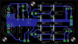
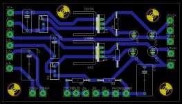
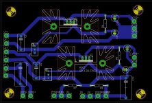
OK, I went back to the drawing board. I redid both boards as single-sided and left the SSHV portion up to the people who know better than me. What's left is 2 boards that make up the Valve Itch power supply, AC and DC.
I've ordered some SSHV v2 boards to go with these. That's definitely the smart way to go since the SSHV v2 board looks so good.
The T connections are from the transformer and the U connections are the umbilical cord between these two boards. The SSHV+/- connections correspond to the Raw DC inputs of the SSHV board. The GND connections are where I will ground to the chassis. The rest should be self explanatory.
So, is this pair of boards any better than my last attempt?
Attachments
Thanks! I added bigger heatsinks and made the board a little bigger. I really appreciate you sharing your expertise.Your LM317T sinks are not big enough. You gonna need 3.8C/W at least.
No, I'm going to wire that section point to point. A PCB seems like it's much easier for the power supply since so many of the components are surface mount and require heatsinks and all that. Stringing resistors and capacitors across tube sockets and standoffs isn't too bad.Are you going to draw up a set of boards for the phono stage itself?
Attachments
I'm having trouble deciding on a heatsink for Q3 on the SSHV2 board. Since B+ is 300V, does that mean that there will be little excess current that needs to be dissipated by the Q3 heatsink, and therefore a very large outboard heatsink isn't required? What heatsink would you use for this application?
Last edited:
- Home
- Source & Line
- Analogue Source
- Valve Itch phono