thats the zoom H1 against the zoom H2 with the line in though..... mixed in with the FT-3 teflon caps as bypasses on the output caps and maybe even more....
Nice final result as an update to listen non the less.
Another thing I wanted to ask is about the SUTs. You kept the diagonal ground wire for input cold and output cold, and grounded it to the buss bar start along each signal ground? What about their mu metal cans themselves? Grounded them there too with individual wires and kept them insulated from the chassis, or they find different ground point by contact to chassis through their mounting collars?
Finally!!
new track
older track
One is still louder than the other - 2 notches on my attenuator.... its hard enough to hear much difference, but to me it seems the newer track is tighter on the bass - the strings on the bass sound plucked more than on the older. Also on the second song the drummer hits the snare - that sounds flat on the older track, is snappier on the newer.
Anyway - have a listen and see what you think. I edited them so that they are both the same length more or less and excuse the "glitch" at the start of the new track.
Fran
No - diagonal wires are cut.
The cans themselves are not grounded either - they are on insulated stand-offs.
So, input grounds have 0.01uf ceramic cap to the chassis right at the inputs but other than that they go to the primary on the Tx.
All shields also go to the same chassis point through another 0.01uf cap. Main buss connects to a separate safety earth online the chassis through back to back dioded//power resistor //cap.
Last edited:
Anyway - have a listen and see what you think. I edited them so that they are both the same length more or less and excuse the "glitch" at the start of the new track.
Fran
The new one has more open mids and is more bouncy in the rhythm section, has a bit more detail also. The applause is richer too. There is a single snare background low level hit when they applaud, that one is more in the house acoustic. Later the snare crack is more present, also the organ. Nice to hear Van Morrison on vinyl from an Irish built phono. Fitting.
") http://www.greektube.org/content/view/16365/2/
http://www.greektube.org/content/view/16365/2/If I touch the cans of get very low level hum - but that's it really. Once I got it quiet I left it alone. I know I'm meant to have that diagonal wire in but I can hear no difference with/without it so I left it open.
You essentially had substituted it by tying each shield to each SUT side and then back to a single point.
Oops - should that smoke be there?
Hmm, got to the end of build and started testing. Rather warm resistor just before the HV shunt. Its 6W 120R which I thought should be ok. I have double checked the wiring and it is all as per my plan so I think must be something wrong with my interpretation of this thread. I attach it here. Not exactly a professional diagram but it is functional. I need to approach this with a fresh pair of eyes in the morning else I might end up frying something! Anyone spot obvious errors on this?
Hmm, got to the end of build and started testing. Rather warm resistor just before the HV shunt. Its 6W 120R which I thought should be ok. I have double checked the wiring and it is all as per my plan so I think must be something wrong with my interpretation of this thread. I attach it here. Not exactly a professional diagram but it is functional. I need to approach this with a fresh pair of eyes in the morning else I might end up frying something! Anyone spot obvious errors on this?
Attachments
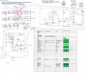
Measure the voltage drop across the 120R. Divide it by 120R. Should be around 5V for a circa 40mA CCS sourcing from that CRC filter. That's only 0.2W. Some 1W resistor should hold forever. If the drop is high and the current is strong then its heating up a 6W resistor enough and gives away wrong current draw down the reg way. Check on reg's R1. Again Vdrop/R. Is it 30-40mA which is wise for the application? If the functioning is OK but the current is much, you should up R1 and current should lower. Else, you got something wrong or burned in the reg. See if you have a burned 9610 if current is wild and won't listen to R1 changes. Check there is about 4V Vgs on the Mosfets. (DVM on G-S). No Vgs=dead. Also wire your 10K LM317 trimmers as shown for R8 in the SSHV, the hand drawn PSU just shows them varying, not exact for connection.
I think I have found the source of the problem. Stupidity on my part. Instead of a 220R to the gate of the IRF840 I used a 220k. That will teach me to be doing this at 2am! Now to see what the damage is I need to test those components that could be suspect. I would have thought the IRF's 9610 and 840. I do not have any spares handy to compare them with so am looking for a way to test prior to ordering replacements on Monday.
I switched the 120R for a very beefy 10K just so I could see if circuit intact. Everything seemed to light up and be stable. Difference across the 10K is 290 ish. I have not got much further with testing rest yet. LEDs are happily lit. I have checked all resistors to make sure all ok and seem to be. It's the 9610 that concerns me. Reading Salas last post if I change values of R1 I should be able to see if 9610 is intact. I could replace irf9610, the 840 and mje350 just for good measure. I have googled how to test these and seems playing with 9v battery is best way if taking them out of circuit. That will be next step if cannot prove they are intact tomorrow. Anyway valves all glowing reassuringly so looks pretty of nothing else. I will let you know how further testing goes tomorrow. Thanks all.
. I will let you know how further testing goes tomorrow. Thanks all.290V across 10K means 29mA. Which sounds normal with your R1. I told you, you may measure voltage difference between gate and source of each Mosfet when the circuit is alive. You should find ~4V if they are OK. Get rid of D1 to make sure it does not perplex things and check with a CRC resistor value that brings 320V DC in to the reg and adjust for 300V DC out. Say 1K 3-5W.
- Home
- Source & Line
- Analogue Source
- Valve Itch phono