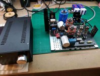
The power supply in the latest version is much simpler to save the space (CLC). I believe this resulted in a bit muddier bass. In the first version it was cLCLC. But the difference is very subtle I would say. Maybe as Salas said there were/are some parasitic capacitances.
I haven't done any testing yet btw.
I haven't done any testing yet btw.
There is always parasitic capacitance in layout styles but I wonder how different between each p2p build and the specific board.
It maybe changes the input capacitance or second stage's Miller effect a bit. If there is measurable difference in the response between p2p and board builds it can be adjusted by tweaking C3 value.
But that is in the same area of how much treble preference also. Other changes between builds like in the PSU configuration may bring differences of course.
Finally did some side by side with my Graham Slee Reflex M. First of all, I was shocked that the Valve Itch is significantly quieter. I had always thought the Slee a bit “thin” in my system and the test bore this out. The Valve Itch is incredibly accurate but just extracts a richness of detail that the Slee doesn’t. I’m listening to the new MoFi one step of Mingus Ah Um, which is a remarkably layered, complex recording. On Better Got It in Your Soul there is a presence with the Valve Itch — air between the horns in collective improvisation, the cymbals crackling with tremendous accuracy, and Charles Mingus himself shouting in my room. These details were there with the Slee, but with less lifelike presence. Then on the somber ballad, Goodbye Pork Pie Hat, the gooey midrange comes out, but the air and space remains.
Anyway, just some listening notes. I am really enjoying this thing.
Rest of system:
Hana SH > Rega P8 > Valve Itch > Rogue Cronus Magnum II > Harbeth 30.1
Anyway, just some listening notes. I am really enjoying this thing.
Rest of system:
Hana SH > Rega P8 > Valve Itch > Rogue Cronus Magnum II > Harbeth 30.1
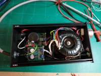
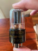
Took me some time, but finished assembly my itch too. Only power supply has a box for the moment and have to find a nice one for the main amp in the future.
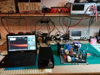
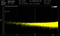
I attach also some measurements I took, a zoomed RIAA response and an FFT.
THD+N drops about tenfold if you up the output voltage to one volt.
Also at the end I had to shield the small tubes and C4 capacitor for a cleaner FFT. Some spikes at the top will be dealt with when in a proper box.
Hopefully will have a listen with a shure V5 type III with a generic needle (no Jico for the moment!) the next few days.
Attachments
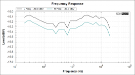
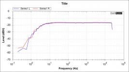
Very good noise floor and excellent RIAA tolerance for measuring an open plan tube phono build George. Congratulations.
Your little HF spikes to the right of your yellow FFT chart should be bench interference picked by either input valves or most likely by the inter-stage capacitors. Boxing and/or close shielding may eradicate them. Hum related needles at the lows are already almost absent. Excellent result in that commonly troublesome area. Jphabc54's remarks on surprising quietness and response accuracy to the ear you backed them up with some measurements now.
Do you have an up close 0dBV (1VRMS) 1kHz FFT so we could maybe discern the real THD spikes coming up from the noise floor?
Very good noise floor and excellent RIAA tolerance for measuring an open plan tube phono build George. Congratulations.
Your little HF spikes to the right of your yellow FFT chart should be bench interference picked by either input valves or most likely by the inter-stage capacitors. Boxing and/or close shielding may eradicate them. Hum related needles at the lows are already almost absent. Excellent result in that commonly troublesome area. Jphabc54's remarks on surprising quietness and response accuracy to the ear you backed them up with some measurements now.
Do you have an up close 0dBV (1VRMS) 1kHz FFT so we could maybe discern the real THD spikes coming up from the noise floor?
I did one with 1vrms, but did not record it. Maybe later.
By the way, in case you did, don't use the anti-Riaa software filter for evaluating response when doing the 1kHz THD FFT.
Thanks for the tip and the support so far!
Because such a software filter in order to evaluate response against an EQ standard (Riaa) shows the phono noise flat on the display without being there as such in reality. The mid & lows grass should be getting gradually higher than the highs grass, roughly following the Riaa curve as noise floor when measured untouched by software EQ.
Its not working like a hardware anti-Riaa that prefilters the test signal to the phono's opposite way. It simply plots the phono's internal Riaa deviations vs a mathematically perfect phono EQ filter. Your test source signal is still flat.
Its not working like a hardware anti-Riaa that prefilters the test signal to the phono's opposite way. It simply plots the phono's internal Riaa deviations vs a mathematically perfect phono EQ filter. Your test source signal is still flat.
I took some more measurements, this time with a 40dB resistor attenuator.
I noticed that the generator of the QA401 is not so clean to 5mV and absolute useless at less than 1mV to measure MC preamplifiers. That' s also the reason for the low gain shown.
The spikes are gone and everything looks as it should and keep in mind that the pre is not boxed yet.
There is an anti RIAA software filter though.
I will have a listen soon. What loading do you suggest for a Shure V15 type3?
Attachments
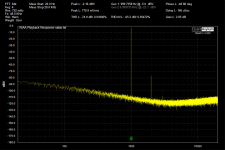
Very clean Itch noise floor output now with a hardware attenuator used. Divides the digital generator's noise as much as its amplitude. Test signal got cleansed, doesn't add nasties.
Yes, it should fool the software by missing 40dB from reported gain at the top left corner. There is 1/100 signal drop happening in your L-Pad it doesn't know about. Thinks test signal remains 500mV as it sends it out to the phono but its cut down to 5mV along the way. Still all the other numbers shown in the screenshot are valid because only relevant to what it sees back from the phono.
The THD profile is dead giveaway tube by the way. All things as expected.
About best loading the Shure V15 others will tell you. Me I had its antagonist the Stanton 881S back in the day
I took some more measurements, this time with a 40dB resistor attenuator.
I noticed that the generator of the QA401 is not so clean to 5mV and absolute useless at less than 1mV to measure MC preamplifiers. That' s also the reason for the low gain shown.
The spikes are gone and everything looks as it should and keep in mind that the pre is not boxed yet.
There is an anti RIAA software filter though.
I will have a listen soon. What loading do you suggest for a Shure V15 type3?
Shure manual
V-15 Type 111 and V15 111-G
Typical Trackability (cmlsec peak recorded velocity at 1 gram in Shure-SME Tone Arm). Reference: Shure TTR 103 Laboratory Test Record.
400 Hz-26 cmlsec 5000 Hz-35 cmlsec 1000 Hz-38 cmlsec 10,000 Hz-26 cmlsec
Frequency Response (using Optimum Load): 10 to 25,000 Hz
Output Voltage: 3.5 mV per channel at 1000 Hz, 5 cm/sec peak re- corded velocity. Output from each channel within 2 dB
Channel Separation: Minimum 25 dB at 1000 Hz Minimum 15 dB at 10,000 Hz
Tracking Force Range: '14 to 1'14 grams
Optimum Load: 47,000 ohms resistance in parallel with 400 to 500 picofarads total capacitance per channel. Load resist- ance can be up to 70,000 ohms with almost no audible change in frequency response. Total capacitance in- cludes both the tone arm wiring and amplifier input circuit. (Most amplifiers and tone arms meet this requirement.)
Inductance: 500 millihenries
Attachments
- Home
- Source & Line
- Analogue Source
- Valve Itch phono