The current mirror is not a CCS for the zener, it turns the current around and buffers the load resistor, while still leaving a relatively low impedance in series with the zener for max loop gain. The bandwidth can be inferred from the response data given earlier. I don't know what the output noise is, but according to measurements done by other DIY members, a 30V zener is probably the lowest noise simple reference availabe.
BTW, I have contemplated unbalancing the resistors in the current mirror of my shunt regulator, leaving the 10 ohm in the half in series with the zener, but upping the series resistor on the other half to 50-100 ohms. This would force more current through the zener, lowering its noise and incremental impedance. Right now, the zener is running at ~1 mA quiescent current, which is a little low.
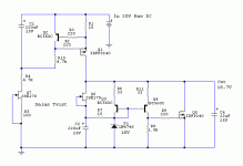
I pushed the values to 4.7 ohms on the zener side and 100 ohms on the other. That gets me 10 mils through the zener and 1 mil on the other side - mind you, that's using my circuit with the extra PNP gain stage. Your mileage may vary.
10 mils is ok for a 1W zener like the 1N4751A. You'd want to push only 5 mils or so through a 500 mW part.
10 mils is ok for a 1W zener like the 1N4751A. You'd want to push only 5 mils or so through a 500 mW part.

What is your hunch as to why simple, rather well done shunts are so noticeably better sonically to some of us on any audio application?
Yesterday a friend called me late at night to tell me that his T-Amp doubled its soundstage and fluency and kick in the lows, after he put together a 2.5A simple Mosfet shunt I designed him to try. Can all we be out of our heads? He lives across the south sea, does not listen to my stuff.
Yesterday a friend called me late at night to tell me that his T-Amp doubled its soundstage and fluency and kick in the lows, after he put together a 2.5A simple Mosfet shunt I designed him to try. Can all we be out of our heads? He lives across the south sea, does not listen to my stuff.
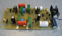
I finally got off my butt and finished this project with a new board that incorporates the regulator shown in this thread. I powered it up last night, and the static bias voltages are right on the money. Next thing is to run the frequency response curves. I'm using the Russian K71-7 polystyrenes and selected Roederstein MKP1840 polypropylenes for the equalization capacitors. The orange caps are BC 1uF polypropylenes (probably MKP 479 series) used for coupling between stages.
Attachments
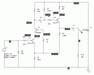
On a whim, I relaxed my policy of minimizing the number of exotic Japanese fets and put together a complementary pair input stage using the 2SK170 and 2SJ74, with a PN4391 to cascode the 2SK170. Schematic and quiescent operating points are shown here. I hoped to remove a buffer stage and reduce the number of active devices I'm currently using. The second stage doesn't really need a follower, as the only load it will see is a 50k pot. This chage would reduce the total number of active devices/channel from 8 to 5.
Attachments
Last edited:
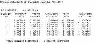
I spoke a bit too soon - the loading of the circuit makes a difference in overall THD and the level of high order harmonics. With that in mind, I'm going to play mix-and-match with buffers and the various gain blocks I've accumulated over the years to see what simulates the best in terms of benign THD and harmonic distribution. Only then will it be time to build another preamp.
Hi,
I think I mentioned the BF246 series before. Lownoise, high Idss, high gm, fast, low capacitance parts and ease avaliable standard from Fairchild NXP and Infineon (as BF247 from NXP with changed pinout).
Suffix A means a Idss range from 30mA-80mA at an Vgs of >1.8V.
So You could use these instead of J2 and J3.
Possible changes to the circuit.
- replacing J3 with an BF246A
- omitting C2 and R7 (if needed, changing values of R1 and R6 for the desired gain and Bias)
- replacing R3, R4 and J2 by a currentsource loaded sourcefollower of two BF246A (source resistances of 75 to 150Ohms should fit to run on 10mA-20mA Bias current) giving an output impedance of ~25Ohms+ source resistance.
That should solve the loading problem.
jauu
Calvin
The BF246 is a euro device, and harder for me to get. It's also only good for 25V. I would sub the J310, as I have piles of those. The PN4393 works quite well for J3, and I have hundreds. They also have high IDSS and low input capacitance (as well as a 40V rating), They (and the family PN4391-4393) were designed as high speed choppers, but work quite well as linear devices. They are still available from some of the usual suspects and as NOS.
The cap and resistor are there so that input and output stages can be biased independently . Try setting the output quiescent voltage at 1/2 VCC (or even close, something I insist on doing for the second stage of an RIAA amp) without them. I'm making a separate study of various gain blocks I've looked at over the course of about 4 years with and without buffers, and will post results as I grind them out. My standard buffer is a current-source loaded follower using a pair of PN4393. Works quite well, and I have hundreds. I also may try using the PN4393 and J176 in the first stage of the amp to dump the hard-to-get Japanese fets. The pair acquits itself fairly well in the amplifier second stage, and will no doubt have a lower THD with the smaller signal excursion of the first stage. More diddling yet to come...
The cap and resistor are there so that input and output stages can be biased independently . Try setting the output quiescent voltage at 1/2 VCC (or even close, something I insist on doing for the second stage of an RIAA amp) without them. I'm making a separate study of various gain blocks I've looked at over the course of about 4 years with and without buffers, and will post results as I grind them out. My standard buffer is a current-source loaded follower using a pair of PN4393. Works quite well, and I have hundreds. I also may try using the PN4393 and J176 in the first stage of the amp to dump the hard-to-get Japanese fets. The pair acquits itself fairly well in the amplifier second stage, and will no doubt have a lower THD with the smaller signal excursion of the first stage. More diddling yet to come...
The ground rules for the presentations to follow:
1) Circuits here are intended for a passively equalized RIAA preamp for use with MM cartridges or high output MC (or other cartridges such as the Grado MI cartridges that have similar output voltage to the standard MM types). Architecture is front stage - eq network - output stage. I won't bother with doing anything for low output MC cartridges until I bag one for myself (not at the top of my to-do list). Frankly, I don't think I've exhausted the possibilities of my Grado Gold just yet.
2) Preamp will drive a 50k output impedance (a volume pot in this case). Why do you need a phono preamp that can fire up a toaster, anyway...
3) Front stage gain is ~40X, output stage ~30X. With the passive EQ network in between the two, this yields an overall gain of ~40 dB at 1kHz.
4) Supply voltage is +30V.
You are of course free to take the simulations presented here and tweak them to your own operating conditions (LTSpice is free, after all...). The ground rules here represent the conditions in my test bed preamp, and will be used so that all the circuits here have a level playing field (It also preserves my sanity, such as it is).
- Status
- This old topic is closed. If you want to reopen this topic, contact a moderator using the "Report Post" button.
- Home
- Source & Line
- Analogue Source
- Yet Another JFET Phono Preamp