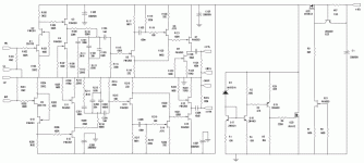
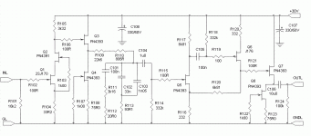
Attached is a schematic for a passive equalization RIAA preamp using a buffered cascoded common source input (like a Pacific with a couple of bows and ribbons), and a complementary feedback pair for the second stage after the EQ network.
I've been working over the past three years on various schemes for the second stage(after the EQ network) to replace the common source stage used by the Pacific, which has relatively high distortion when forced to pump out a volt or two. Some of the things I've tried are a heavily biased small signal MOSFET (see the "All American" thread), and using optimally loaded JFET SRPP stages. The complementary feedback pair I'm trying here simulates very well, and since the two halves of the pair are not direct coupled, the JFETs are relatively easy to select. BTW, lest you complain about the interstage coupling cap, it's there so that both stages can be optimally biased for gain and voltage swing.
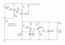
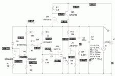
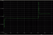
The amp is in the advanced prototyping stage right now. I'm very curious as to how It'll sound. This will also be a test for the new fancy-pants shunt regulator shown in the schematic. It simulates as having ~3 milliohms static output impedance, and recovery time is extremely fast (1-2 usec) for a 100 mA load step with 500 nsec edges.
Attachments
Thorough engineering as always from you Wrenchone. Curious to know about your soon to be made subjective tests too. The shunt part is nice, I know it will do well, because a very recent one that I posted for the Pass B1 looks topologically similar enough, and a DIY audio member had excellent practical results with a quick mock up, used for the almost no PSRR Pass BOZ preamp. And yours is faster.
Attachments
More gain, more RIAA accuracy. Without the buffer, the impedance driving the EQ network is the drain load resistor in parallel with the drain impedance, and you need to adjust the first resistor in the EQ train to account for this. The cascoding raises the drain impedance, but it ain't infinite. With the buffer there is no guesswork, and more consistency unit to unit. In a pinch, you could get rid of the buffer - it's more useful if the input stage is not cascoded.
So if RIAA conformance is the issue, then the 22k6 can be tweaked?
What's the gain difference? Gain is about gmRload, and Rload is just changed from 3k3 to 2k88. That calculates to 1.2dB, and you have to add four active devices in the signal path. Do you lose as much on noise as you gain on gain? I don't know the noise specs of the follower devices.
What's the gain difference? Gain is about gmRload, and Rload is just changed from 3k3 to 2k88. That calculates to 1.2dB, and you have to add four active devices in the signal path. Do you lose as much on noise as you gain on gain? I don't know the noise specs of the follower devices.
In a word, yes. You'll lose a little gain due to loading, but not all that much. My simulations don't show much of an effect on distortion magnitude or distribution by including the buffer. I haven't tried listening tests with and without. Without the buffer, I'd just use a reverse RIAA network and tweak for flat response.
The PN4393s are nominally chopper FETs, but they make pretty good low noise amps for a person on a budget they aren't anywhere near as quiet as the 2SK170, but they are adequate for MM applications, say in the second stage of a MM preamp.
The PN4393s are nominally chopper FETs, but they make pretty good low noise amps for a person on a budget they aren't anywhere near as quiet as the 2SK170, but they are adequate for MM applications, say in the second stage of a MM preamp.
Here is the transient response of the circuit. It takes good low impedance output capacitors to get optimum response. The value shown for output filter (660uF, 11 mohm), would be the value you get from two parallel Panasonic FM series caps, 330uF, 50V. The extra PNP gain stage is what really peps up this regulator.
Attachments
A well balanced cart. On a good TT and arm is no slouch. What TT and arm? I also liked that little amp of yours with the shunt under the cathode instead of self bias or LEDs. I guess with efficient speakers, this phono combined with that amp is gonna sound very immediate and alive. Can it be driven directly from your phono with just a pot? Sensitive enough? You have the phono buffered already. Wishing you a great actual test with very little or no changes.
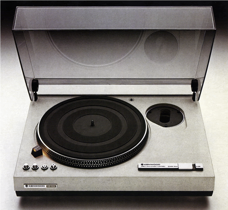
I'm using a Kenwood KD2055, which is ok, but nothing to get excited about. I have a KD500 with no arm, and some SME3009-R arms. I wanted to put one together using an aftermarket bronze bearing to replace the stock nylon bearing and a carbon fiber head shell.
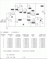
Attached are some simulation results for my preamp second stage - much lower distortion than a simple common source stage for the same output level.
Attached are some simulation results for my preamp second stage - much lower distortion than a simple common source stage for the same output level.
Attachments
I would only use the simulation results for indication purposes. The only thing I would conclude at this point is that the higher order products are likely to be low amplitude.
I could drive my little amp directly from the preamp, but I have no speakers efficient enough at this time to make the exercise worthwhile.
I could drive my little amp directly from the preamp, but I have no speakers efficient enough at this time to make the exercise worthwhile.
I would make a Hemp FR8 Mass loaded TL. Very easy, would add an affordable Tangband Ribbon above 10kHz for sparkle. 94dB after baffle step correction, easy 8 ohm load, no imp dips. Can be done in a weekend if veneering isn't required. Goes deep, great focus point source all over psycho acoustically critical bands. Great TT for restoration you got by the way. Proper speakers, your 500 and the rewired SME will really highlight your excellent electronics.

Hi Wrenchone,
nice to see the journey proceeding!
What is your reasoning for chosing a current mirror as a ccs for the voltage reference zener? (as opposed to a fet or led/transitor based solution, for instance)
What is the bandwith and the noise performance of the regulator?
Thanks,
Rüdiger
nice to see the journey proceeding!
What is your reasoning for chosing a current mirror as a ccs for the voltage reference zener? (as opposed to a fet or led/transitor based solution, for instance)
What is the bandwith and the noise performance of the regulator?
Thanks,
Rüdiger
- Status
- This old topic is closed. If you want to reopen this topic, contact a moderator using the "Report Post" button.
- Home
- Source & Line
- Analogue Source
- Yet Another JFET Phono Preamp
