Thought I might post a pic or 2 of the boards before I close up the box. The bennics are staying and I soldered them in a bit more neatly before shutting up the case.
And the case is one that had previously housed a phonoclone BE. Power supply is in the second box.
Fran
An externally hosted image should be here but it was not working when we last tested it.
An externally hosted image should be here but it was not working when we last tested it.
And the case is one that had previously housed a phonoclone BE. Power supply is in the second box.
An externally hosted image should be here but it was not working when we last tested it.
An externally hosted image should be here but it was not working when we last tested it.
Fran
woodturner-fran, I cleaned my mail box. You can send the file. Very nice enclosures you have. Like a little Halcro.
I made some measurements today on my PhonoClone3 PCB. Here the results:
Source: Line Test Set HP4935A
Transformer secondary, 135ohms Zout
I know it is not a MC cartridge, higher impedance and all, but that will affect mainly the gain, not the freq. response. And it is still a transformer...
Gain: 44.1dB (with this source, would be different with an actual MC cartridge)
Noise (gnd input), measured using a -90dB 1Khz test noise source
30dBrn (C-Filter), or -60dB (-90+30=-60dB noise floor)
46 dBrn (15 Khz flat), or -44 dB
This is with a PCB setting on the bench, without proper shielding and flying wires. I'm also using a workbench power supply. It internal noise would had somehow to the preamp residual noise.
Vout MAX: No result yet.
Zout (Ref 1Khz, 1V): 50 ohms, would be able the drive a normal preamp input and interconnect without problem.
RIAA Curve (Both PCB)
Theoric
HZ dB Output (dB)
20 19.91 17.3 (Could be limited by the coupling cap and/or my test setup
50 16.94 16.4
100 13.09 12.8
200 8.22 8.1
500 2.65 2.6
1K 0 (Ref) 0 (Ref)
2K -2.583 -2.5
5K -8.168 -8.2
10K -13.566 -13.8
20K -18.98 -19.8
50K -24.54 -27.9
Supply Currents: +/- 12.5ma
comments on test methodology:
The best way is to put a voltage divider made up of a 110kohm resistor on top and a 33ohm resistor on bottom between your signal source generator and the phonoclone.
If you put a 1V sinewave on the top of the divider, you get a 0.3 mV voltage out with an inpedance of 33 ohms, a reasonable approximation of the MC cartridge at 1 kHz, and the phonoclone will response with a realistic gain and thus frequency response.
Adjust the values to taste, but that's the basic idea.
Also note the bass response varies with the phonoclone's output load, so make sure it is realistic - say 10 kohms.
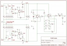
Sorry to point that out, Please check my findings, but I think there is a big error on the schematic and PCB silkscreen. This error is in the power supply section, 4 capacitors are illustrated in reverse polarity, and the silkscreen reflect that.
I was having problem with my boards supplies and asked to send me his boards readings. That confirm that I was having a problem. Problem was that C10 to C13 where connected in reversed and where loading the voltage dividers R12,14,16 (Pos) and R11,13,15 (Neg)
Refer to the normal voltage readings included during the discussion:
Look at the supply positive section for example (IC3,Q1). R12-R13 forms a classic voltage divider, referenced to ground by R16.
This divider is feed with Negative voltage, here -15.8V. So, middle of R12,R13 is roughly at half -15.8V, here -8V. But this negative voltage is filtered by polarized electrolytic, connected on the cap's positive side! So, C10 and C12 are reversed connected. Same thing for the negative side C11, C13.
In my case, C10, C11 where loading the divider so badly that I had only about 4V there instead of 8V. I was scratching my head because my PCB followed exactly the
publish schematic and PCB design.
Correction should be to reverse C10 to C13 polarity and to reverse the silkscreen image on the PCB.
Please correct me if I'm wrong, but there is no way it could work correctly as it is, at least it was not working for me.
Attachments
You are of course correct. Ouch. That explains the break-in issues: the capacitor electrodes were reforming under reverse voltage. The working voltages were low enough that they didn't blow up. I can't believe I missed that. Sorry everyone.
Corrected eagle files attached.
I will propagate the corrections through the web pages etc over the weekend.
Corrected eagle files attached.
I will propagate the corrections through the web pages etc over the weekend.
Attachments
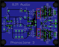
Same deal for the Phonoclone 3 beta board, 30n.
Corrected files attached. It is recommended (starting with yours truly) that the affected capacitors (C10-13) be replaced with new parts positioned in the correct orientation.
To Fran and the other beta testers: I will mail you 4 new capacitors if you need them.
/R
Corrected files attached. It is recommended (starting with yours truly) that the affected capacitors (C10-13) be replaced with new parts positioned in the correct orientation.
To Fran and the other beta testers: I will mail you 4 new capacitors if you need them.
/R
Attachments
")
Thought I'd post what I said in an email to RJM.
4 out of the 8 affected caps (ie 4 on each board) were bulging in my phonoclone 3. Thing is i can't remmber now were they C10/11 or C8/9!
Anyway, the other 4 are fine, and they measure fine. Those bulging ones though only measure 80uF.
So a question now.... will these see the full 16-18V of the PS or could I get away with 16V rated caps? I ahve a stock of 1000uF 16V caps to hand I could use. Is there any problem with going higher in capacitance?
Fran
EDIT: i rooted out some pics I took and it seems that C8 and C9 were the ones that were bulging.
Good practice is always to use a cap volt rating that exceed the highest voltages that the cap will see. That may also include failing parts before the cap that may blow and affect the cap downstream.
For example, if the Transfo/Rectifier supply in the PhonoClone is about 17-18V, then use 25V cap.
To use a cap barely standing on its volt rating may (depending on cap) reduce its useful life, cause premature failure, etc...
In real life, with commercial product, and cost retrained design, caps are often just on low side (smaller, cheaper, etc), for example 6V cap on 5V supply. But for us, since we are building it, in single quantity, better quality target (I suppose), etc, better be safe than sorry...
woodturner-fran said:EDIT: i rooted out some pics I took and it seems that C8 and C9 were the ones that were bulging. [/B]
Mine also. Not hemispherical, but if you looked closely the swelling is plain. These are the ones that see about 8 volts. The other two only see about half a volt, so are unlikely to be damaged by the reverse bias... but as a precaution should still be replaced rather than reoriented.
[note: affected caps in beta board are C8-11, in Rhys' kit C10-13]
How did the error occur and pass the beta test? Aftermath report:
1. The schematic in Eagle was crowded, and I arranged things for neatness rather than comprehensibility. The Xreg circuit mixes the positive and negative power supply circuits, so it's no longer the common case where all the capacitors on the positive rail are drawn in the same direction... but it looks ok at a glance, since people are used to this convention.
2. The reverse voltage is low enough that the capacitors don't critically fail ... they leak badly for a short while, then firm up such that leakage (in my case) didn't affect the circuit voltages enough for me to pick up that something was wrong. I noticed some strange measurements when I first powered it up, but (foolishly) put it down do the capacitors forming .. when I remeasured later everything was basically ok, so I let it go. Fortunately for everyone, Algar-emi's capacitors were less well behaved, and he was careful to measure the situation.
The damaged capacitor compared to a new one:
My phonoclone 3 30n, after the new capacitors were installed:
An externally hosted image should be here but it was not working when we last tested it.
My phonoclone 3 30n, after the new capacitors were installed:
An externally hosted image should be here but it was not working when we last tested it.
Phonoclone rev. 32b
The changes are mainly in the layout of the circuit schematic, to try and make it more intuitive to figure out what's going on.
Phonoclone schematic 32b (.png image)
The changes are mainly in the layout of the circuit schematic, to try and make it more intuitive to figure out what's going on.
Phonoclone schematic 32b (.png image)
Attachments
- Status
- This old topic is closed. If you want to reopen this topic, contact a moderator using the "Report Post" button.
- Home
- Source & Line
- Analogue Source
- Phonoclone 3