Re: Re: Re: Re: Moving Coil
Oh good, we wouldn't want you changing the laws of physics without telling the rest of us.")
scott wurcer said:Try .00001Hz, I have. Had to prove that some wierd noise eventually went back to 1/f, it did and physics was safe again.
Oh good, we wouldn't want you changing the laws of physics without telling the rest of us.
Re: Moving Magnet
Syn08 -
what kind of SNR (rel 0.5mV for MC and 5mV for MM) 20 Hz - 20kHz would those curves translate to with input short circuited?
Looks like a dual mono design, yes?
Sigurd
Syn08 -
what kind of SNR (rel 0.5mV for MC and 5mV for MM) 20 Hz - 20kHz would those curves translate to with input short circuited?
Looks like a dual mono design, yes?
Sigurd
syn08 said:Moving Magnet, gain @1KHz is 44dB
AD797 + AD797 + LME49710
OPA637 in the power supply
Re: Re: Moving Magnet
I don't think you can get this from the straight from the previously posted results. Anyway, the measured S/N's are:
0.5mV MC unweighted 20Hz-20KHz 71dB
2.5mV MM unweighted 20Hz-20KHz 84dB
To go lower, more JFETs need to be paralleled in the input stage. Just for fun (I don't think there would be any subjective improvement) I tried 4x2SK170 and the above numbers went down to 75dB and 88dB. Six or more 2SK170 in parallel, stability at very high HF (over 100MHz) becomes an issue.
Distortions are not really important here, I haven't looked closer, but it's anyway under 0.005%v at 1V output.
Not sure what you mean by "dual mono" in this context. The power input takes 24VDC from a wall wart, splits to +/-12V using a TLE2426 virtual ground and then each rail is fed to a Jung super regulator, common for both channels. Crosstalk is measured under -100dB (still need to take a closer look at this).
I spent the weekend doing comparative noise measurements with three other solid state phono preamps, one is a $100 model, one is a $3000 model and one is a $1500 model, all new. I'll post the results later today.
The best combination so far is AD797+AD797+OPA627 and 2xOPA637 in the Jung super regulator.
Sigurd Ruschkow said:
what kind of SNR (rel 0.5mV for MC and 5mV for MM) 20 Hz - 20kHz would those curves translate to with input short circuited?
Looks like a dual mono design, yes?
I don't think you can get this from the straight from the previously posted results. Anyway, the measured S/N's are:
0.5mV MC unweighted 20Hz-20KHz 71dB
2.5mV MM unweighted 20Hz-20KHz 84dB
To go lower, more JFETs need to be paralleled in the input stage. Just for fun (I don't think there would be any subjective improvement) I tried 4x2SK170 and the above numbers went down to 75dB and 88dB. Six or more 2SK170 in parallel, stability at very high HF (over 100MHz) becomes an issue.
Distortions are not really important here, I haven't looked closer, but it's anyway under 0.005%v at 1V output.
Not sure what you mean by "dual mono" in this context. The power input takes 24VDC from a wall wart, splits to +/-12V using a TLE2426 virtual ground and then each rail is fed to a Jung super regulator, common for both channels. Crosstalk is measured under -100dB (still need to take a closer look at this).
I spent the weekend doing comparative noise measurements with three other solid state phono preamps, one is a $100 model, one is a $3000 model and one is a $1500 model, all new. I'll post the results later today.
The best combination so far is AD797+AD797+OPA627 and 2xOPA637 in the Jung super regulator.
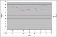
Here's the promised comparison. I won't disclose the manufacturer's brands and models, but only the current prices (brand new). Enough to know they are all brand names, while B and C are highly regarded in Stereophile and other reviews. I don't have the schematics for any of the A, B and C so I can only speculate about their internal architecture.
A - "Low end", $100
B - "Mid Fi", $1600
C - "High End", $3000
All S/N numbers are 20Hz-20KHz unweighted, 2.5mV input for MM and 0.5mV input for MC.
Looking at the MM results, the differences between models are significant. My assumption is that the low performers (A, B) are using a regular opamp input stage, hence the poor noise performance.
Looking at the MC results, it seems like B and C are using the same input stage (so does GPP) and switches the gain downstream. Model A seems to switch/add a low(er) noise input (bipolar discrete? it certainly doesn't seem to be a low noise JFET design) stage, the S/N difference between MM and MC is very small.
But what seems to be really interesting is the very small gap between GPP, A and B MC S/N. Now, you tell me if this gap is worth $1500 difference between models A and B?
Experimentally, GPP may reach the Model C performance if upgraded to 4x2SK170 in the input stage. But 2SK170 are close to unobtanium, so other ways have to be developed. Two questions arise here:
- Is the performance gap between 2SK170 and any other solution worth anything but a nice spec sheet?
- If such performances are really worth of, how to proceed from here?
Next steps are a MM/MC phono stage based entirely on opamps (and see if there's any subjective difference), and if so, then exploring alternatives to the 2SK170 input stage.
Attachments
71 dB SNR rel 0.5mV is OK, and excellent for a first design, but I would not settle for that when designing such a fairly complex RIAA amp as yours. Especially as I would design an MC-only RIAA amp for low resistance cartridges (<10 Ohm) with <= 0.5mV output voltage.
You might want to try low noise parallelled bipolars for the input stage. THAT has some low noise types, or you can try the 2SC2545,6,7E.
The 2SK170 are not hard to get at all. I do not understand that you find them close to unobtanium.....even the 2SJ74 are easy to find.
I would say that if you have a low resistance low output MC cartridge needing maybe 90dB of gain a low freq, more SNR can come in handy.
There are much more than SNR - how does it sound is the most important issue.
Overload issues are also important.
RIAA accuracy of course.
SIgurd
syn08 said:- If such performances are really worth of, how to proceed from here?
Transformers?
Syn08, there might be another possibility here. since the JFET you are using is ultra-quiet, it pays to put as muchof the verall gain in the quiet front end stage as possible. So, I would experiment with increasing the JFET + first op-amp circuit block stage gain. Tradeoffs are required, but if its low noise you are after, this is one way.
The attached input stage will give an SNR of about 77 dB rel 0.5mV 20-20kHZ unweighted with RIAA curve using 8 pairs of matched SK170/SJ74BL,
and a very low resistance feedback network and a 5 Ohm pot.
The last few dBs are very hard to achieve. With or without transformers....
Sigurd
and a very low resistance feedback network and a 5 Ohm pot.
The last few dBs are very hard to achieve. With or without transformers....
Sigurd
Attachments

Sigurd Ruschkow said:The attached input stage will give an SNR of about 77 dB rel 0.5mV 20-20kHZ unweighted with RIAA curve using 8 pairs of matched SK170/SJ74BL,
and a very low resistance feedback network and a 5 Ohm pot.
The last few dBs are very hard to achieve. With or without transformers....
Sigurd,
Paralelling more JFETs is the obvious solution in an attempt to gain some extra SNR dBs. Unfortunately I have found significant stability issues when using more than four 2SK170, unless you add some gate resistors which are then, of course, pooping the whole party.
Coincidentally, the Nelson Pass Xono (which I highly regard) AFAIK uses four cascoded 2SK170 in the input stage.
Measurement wise, the Xono design must be one of the lowest noise designs on the market.
-81 dB unweighted rel. to 1mV is indeed extremly low.
Gain at 1kHz is also very high at 76dB. I use 64 dB but then I do not design for the 80uV cartridges.
Looking at the OM for the Xono is seems to use four parallelled devices.
Sigurd
-81 dB unweighted rel. to 1mV is indeed extremly low.
Gain at 1kHz is also very high at 76dB. I use 64 dB but then I do not design for the 80uV cartridges.
Looking at the OM for the Xono is seems to use four parallelled devices.
Sigurd
syn08 said:
Sigurd,
Paralelling more JFETs is the obvious solution in an attempt to gain some extra SNR dBs. Unfortunately I have found significant stability issues when using more than four 2SK170, unless you add some gate resistors which are then, of course, pooping the whole party.
Coincidentally, the Nelson Pass Xono (which I highly regard) AFAIK uses four cascoded 2SK170 in the input stage.
Attachments
Sigurd,
...and a pitiable sound. Innocent attempts to fool physics like this have been made before, always with modest success.The attached input stage will give an SNR of about 77 dB rel 0.5mV 20-20kHZ unweighted...
Hps 2.0
Well, GPP is now re-baptized as HPS (Hybryd Phono Stage)...
HPS 1.0 had already very good performance, however I was looking forward to add a few new features and further improve the overall performance. While HPS 1.0 has under 1nV/rtHz noise (SNR is 71dB for MC and 84dB for MM) and -88dB crosstalk, I was targeting better than that. I already knew that 0.5nV/rtHz requires 4 x 2SK170 in parallel (and, for stability reasons, that's about all you can do without adding gate resistors), but what else? Having a spare 1.0 PCB, I've decided to cannibalize and use it as a "breadboard" to further experiment. The sad news is that going under 1nV/rtHz requires a completely new overall architecture... So it was time for HPS 2.0
First, I had to drop the idea of a wall wart power supply and TLE2426 virtual ground IC, even if followed by Jung super regulators. For whatever reasons, this solutions generates 60Hz harmonics which could be filtered at the output (before the Jung regulators) but unfortunately TLE2426 handles very poorly capacitive loads. It simply becomes unstable...
Secondly, the Jung regulators are pretty effective (having very good line rejection) but some degree of harmonics are still going through... The input stage (see the 1.0 schematic) had basically no PSRR so some of these harmonics appeared at the output. Nothing audible (I am talking here well under 1uV levels) but certainly annoying in measurements.
Third, moving from a wall wart requires a line transformer, so forget about hosting the power supply in the same case with the signal path... And then to add insult to injury, moving to a separate power supply requires extra wiring for sense and sense shielding, otherwise the line and load requlations are strongly affected (see Jung's article http://waltjung.org/PDFs/Improved_PN_Regs.pdf)
Fourth, the input stage could use some PSRR. Therefore, cascoding the JFETs and adding an extra local regulator would certainly help.
Fifth, improving the crosstalk to -90dB and beyond requires some power supply wiring layout changes. Keeping power supply traces, for the L/R channels, separate all along is critical. Note that in practice a -100dB crosstalk for a phono stage doesn't make much sense; a typical cartridge has a crosstalk of -20dB. So improving the original performance was more like a self challenge rather than a requirement.
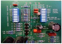
And sixth, while I still don't believe in loading the cartridge with very low inpedance does anything good for the sound, I thought some input flexibility would be a nice feature; I added 4 resistors (10, 100, 499, 1k) and 4 capacitors (100pF, 220pF, 330pF, 470pF) giving 256 combinations of RC input impedances. The default impedance is still 47k/100pF. These are switchable via onboard DIP switches.
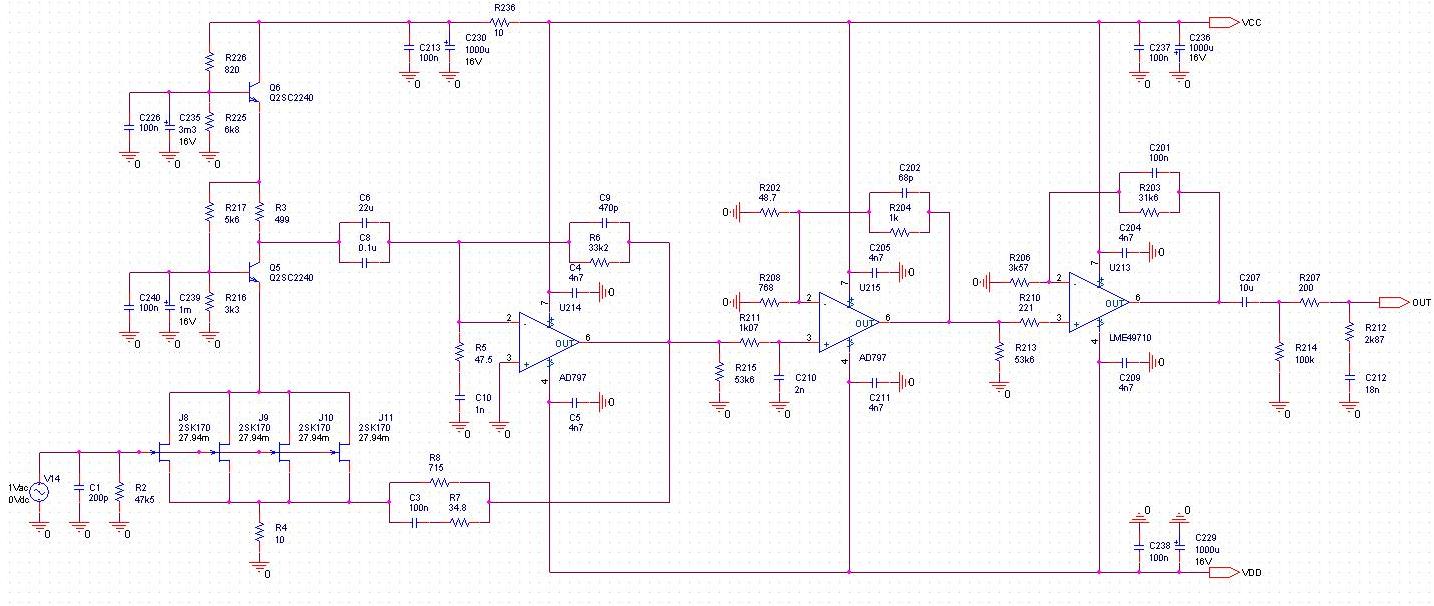
The HPS 2.0 schematic:
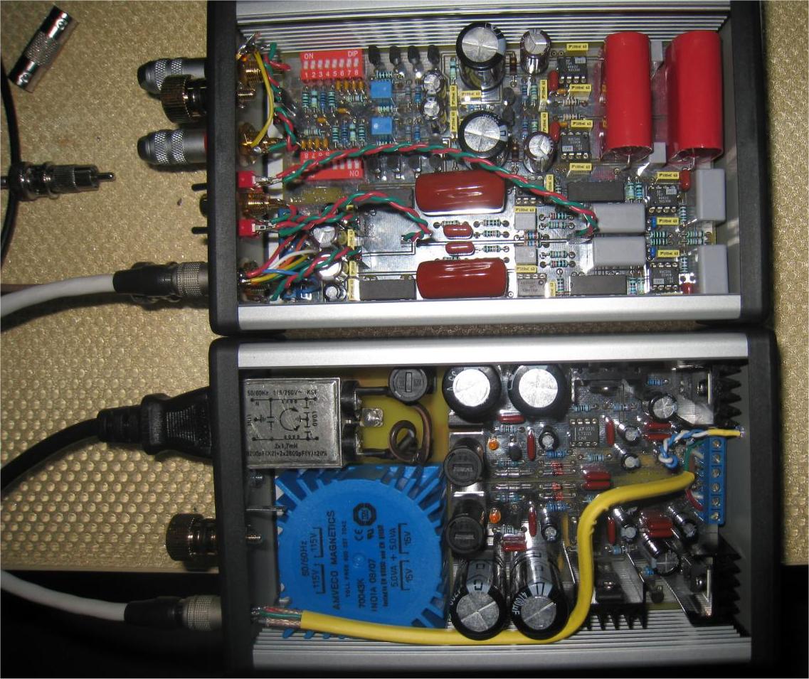
The power supply:
The signal channel:
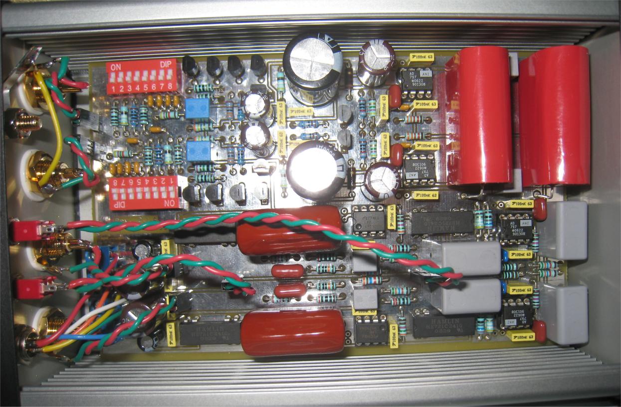
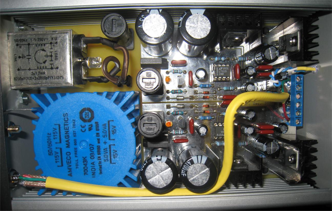
An overall picture of the implementation:
Performance:
Noise:
0.44nV/rtHz @1KHz, both MC and MM
SNR: 89dB MM @ 2.5mV input, 76dB MC @ 0.5mV input
RIAA:
+/-0.15dB 20Hz-20KHz
Crosstalk:
-101dB @1KHz
-97dB @20KHz
Distortion:
Better than 0.002% 20Hz-20KHz
To me, that's about all one can wish from a phono stage. Comments are welcomed.
Well, GPP is now re-baptized as HPS (Hybryd Phono Stage)...
HPS 1.0 had already very good performance, however I was looking forward to add a few new features and further improve the overall performance. While HPS 1.0 has under 1nV/rtHz noise (SNR is 71dB for MC and 84dB for MM) and -88dB crosstalk, I was targeting better than that. I already knew that 0.5nV/rtHz requires 4 x 2SK170 in parallel (and, for stability reasons, that's about all you can do without adding gate resistors), but what else? Having a spare 1.0 PCB, I've decided to cannibalize and use it as a "breadboard" to further experiment. The sad news is that going under 1nV/rtHz requires a completely new overall architecture... So it was time for HPS 2.0
First, I had to drop the idea of a wall wart power supply and TLE2426 virtual ground IC, even if followed by Jung super regulators. For whatever reasons, this solutions generates 60Hz harmonics which could be filtered at the output (before the Jung regulators) but unfortunately TLE2426 handles very poorly capacitive loads. It simply becomes unstable...
Secondly, the Jung regulators are pretty effective (having very good line rejection) but some degree of harmonics are still going through... The input stage (see the 1.0 schematic) had basically no PSRR so some of these harmonics appeared at the output. Nothing audible (I am talking here well under 1uV levels) but certainly annoying in measurements.
Third, moving from a wall wart requires a line transformer, so forget about hosting the power supply in the same case with the signal path... And then to add insult to injury, moving to a separate power supply requires extra wiring for sense and sense shielding, otherwise the line and load requlations are strongly affected (see Jung's article http://waltjung.org/PDFs/Improved_PN_Regs.pdf)
Fourth, the input stage could use some PSRR. Therefore, cascoding the JFETs and adding an extra local regulator would certainly help.
Fifth, improving the crosstalk to -90dB and beyond requires some power supply wiring layout changes. Keeping power supply traces, for the L/R channels, separate all along is critical. Note that in practice a -100dB crosstalk for a phono stage doesn't make much sense; a typical cartridge has a crosstalk of -20dB. So improving the original performance was more like a self challenge rather than a requirement.
And sixth, while I still don't believe in loading the cartridge with very low inpedance does anything good for the sound, I thought some input flexibility would be a nice feature; I added 4 resistors (10, 100, 499, 1k) and 4 capacitors (100pF, 220pF, 330pF, 470pF) giving 256 combinations of RC input impedances. The default impedance is still 47k/100pF. These are switchable via onboard DIP switches.
The HPS 2.0 schematic:
The power supply:
The signal channel:
An overall picture of the implementation:
Performance:
Noise:
0.44nV/rtHz @1KHz, both MC and MM
SNR: 89dB MM @ 2.5mV input, 76dB MC @ 0.5mV input
RIAA:
+/-0.15dB 20Hz-20KHz
Crosstalk:
-101dB @1KHz
-97dB @20KHz
Distortion:
Better than 0.002% 20Hz-20KHz
To me, that's about all one can wish from a phono stage. Comments are welcomed.
analog_sa said:Power transformer is about 20 times smaller than what i use
Superstition.
Re: Hps 2.0
Good to see that you decided to improve the design!
SNR is now so good that it is no problems to use the RIAA with medium output MC cartridges. For MM use 89 dB is not really needed, so one can wonder why not connect an MM cartridge before the JFETs.
The huge red caps in the upper right corner and in the middle, what types are those?
Ideas for improvement could be to have adjustable gain, and adjustable input resistors for MC cartridges (although doing this manually might be the best solution).
BTW,
what gains do you have,
and what are the overload margins?
Sigurd
syn08 said:Well, GPP is now re-baptized as HPS (Hybryd Phono Stage)...
PMA said:We made a listening comparison with very expensive preamp, that uses two 100VA transformers and 164.000 µF filter caps. Anyway, that preamp was assessed as worse in a listening test. The preamp is not about transformer size that much.
We made a similar comparison. Opposite results. Of course comparing wildly different topologies and power supplies is silly. I am only talking of transformer size, everything else kept equal. Had to redo the casing to fit a bigger unit; not something i do lightly.
That input stage is vaguely reminicent of some of the Calrec Soundfield mics one of the few mic circuits I've seen using feedback all the way to the input. Can't complain about your choice of op-amps either
It's hard to morph one of these MC preamps into something for a transformerless ribbon mic circuit. James Boyk of Performance Recordings is high on them these days, one of my back burner projects.
BTW, did you really have no use for the little bit of distortion removal via the 50pf extra cap on the first amp? It's possible there is little or no difference in this circuit.
- Status
- This old topic is closed. If you want to reopen this topic, contact a moderator using the "Report Post" button.
- Home
- Source & Line
- Analogue Source
- GPP - Great Phono Preamp