After some hours I super like the sound of this preamp
How is it going after some days? Still happy?
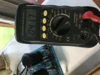
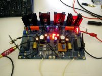
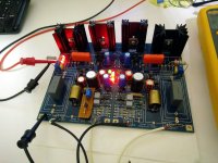
Nice cheap and handy switching PSU modules for general use those. But very noisy indeed. This multiplier did a great ripple eating job at 70kHz as I see in your scope's picture. The second order type has usefully controlled output impedance in the HF too. It skyrockets in high frequencies for those with just a resistor and a cap.
I specifically choose high noise switch PSU (Lambda Alpha 1kW - http://us.tdk-lambda.com/ftp/Specs/alpha1000.pdf) to see how will behave CM with delivered 300mV ripple. Although input noise is high , I'm not sure if DPS5015 buck controller is guilty for it. For sure, it is not adequate filtration on it and would be nice to add some internal noise suppression. BTW, this buck converter is using 60kHz switching frequency which is correlates to scope image Yellow trace. Really want to test CM on one one of my FSPs, but do not want to use perf-board. Would like to make nice PCB.
Hi there/ hi Nick
I'm trying to figure out some parts for the Phono build and i was wondering what is the minimum Voltage for the raw PSU main capacitor. Is 50V ok or is at the edge?
I m trying to figure out the maximum capacitance for the space i have so what is the max allowed diameter for capacitor in this position??
Thanks in advance
Tom
33V AC will make circa 46V DC so its enough for the FSP. Because most reported builds due to bias tolerances tend to use lower than 34V regulated rail, about 12V drop across the reg is also ok to work its CCS well. The 36V transformer spec is to cover low mains official tolerances but many builder's transformers overshoot spec because their mains is most of the time high so people with such Tx usually end up with a resistor instead of the wire link from bridge to reservoir on the raw pcb for extra drop. That resistor also makes a little HF filter with the reservoir as a side benefit though.
In general we prefer no more than 50V raw DC to reach the FSP's onboard regs inputs. Large DCin-DCout drop is good for linearizing the CCS MOSFET regarding its own capacitances but after 12-15V drop its a diminishing return and we inherit a hot CCS sink situation that affects the ambient temperature delta in the box so the drifts go wilder. High raw DC input also puts Q2x to strain.
In general we prefer no more than 50V raw DC to reach the FSP's onboard regs inputs. Large DCin-DCout drop is good for linearizing the CCS MOSFET regarding its own capacitances but after 12-15V drop its a diminishing return and we inherit a hot CCS sink situation that affects the ambient temperature delta in the box so the drifts go wilder. High raw DC input also puts Q2x to strain.
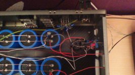
Salas RIAA, MM
One of the best, no doubt!-:
Here within a case of a Luxman 410. For a friend. Drives a Single Mosfet - and
... than out;-))))
Pickup - Speaker: 3 Transes;-)))
Do use ONE PSU for ALL!
AT 91! A wonderful pickup!
1. picture - one side, one channel.
LG
One of the best, no doubt!-:
Here within a case of a Luxman 410. For a friend. Drives a Single Mosfet - and
... than out;-))))
Pickup - Speaker: 3 Transes;-)))
Do use ONE PSU for ALL!
AT 91! A wonderful pickup!
1. picture - one side, one channel.
LG
Attachments
Last edited:
") Is it the Folded circuit or one of the previous? Having all its stages or just the first two?
Is it the Folded circuit or one of the previous? Having all its stages or just the first two?Need help
Hi Salas and all. I have a nearly finished kit that stopped in it’s tracks a few years ago due to life’s unexpected nature. I really would love to finish this project and hear it sing. I live in Australia, nsw, Byron Bay. Does anybody live around me or know of somebody close by who could help complete this kit. Kind regards Mike C
Hi Salas and all. I have a nearly finished kit that stopped in it’s tracks a few years ago due to life’s unexpected nature. I really would love to finish this project and hear it sing. I live in Australia, nsw, Byron Bay. Does anybody live around me or know of somebody close by who could help complete this kit. Kind regards Mike C
Hi Salas,
I tried doing some searches, but this thread has gotten rather long (which is a good thing and sign of the quality!).
I am putting together pieces to build one of these and had a question regarding Q7 2SK117s... I have 17 of these but only 2 that are high enough Idss (one that is 4.2 or so from memory, and another that is 5.5). Could I use 2SK117BL with Idss in the 7s for these?
Thanks!
Hi Salas and all. I have a nearly finished kit that stopped in it’s tracks a few years ago due to life’s unexpected nature. I really would love to finish this project and hear it sing. I live in Australia, nsw, Byron Bay. Does anybody live around me or know of somebody close by who could help complete this kit. Kind regards Mike C
In case you need help in terms of further guidance we can still do it from here.
Hi Salas,
I tried doing some searches, but this thread has gotten rather long (which is a good thing and sign of the quality!).
I am putting together pieces to build one of these and had a question regarding Q7 2SK117s... I have 17 of these but only 2 that are high enough Idss (one that is 4.2 or so from memory, and another that is 5.5). Could I use 2SK117BL with Idss in the 7s for these?
Thanks!
Yes you could. Only change R15 to 2.4k and expect little bit more Vf and light from Leds D1-D4.
In case you need help in terms of further guidance we can still do it from here.
Thanks Salas, you were very helpful when I started. I’ll dig everything out and blow off the dust from my brain. I suppose I was hopeful somebody local to me might have time and the skills required to finish it off. It’s been a while.
Thanks Salas, you were very helpful when I started. I’ll dig everything out and blow off the dust from my brain. I suppose I was hopeful somebody local to me might have time and the skills required to finish it off. It’s been a while.
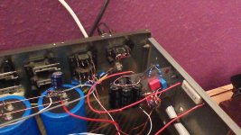
Ok, I’m off again. Psu toroidal 41.7 v ac, this okay?
Attachments
Its high AC. But no worries, because there is provision. Where the raw pcb has the RD/Link marked positions put 47-50 Ohm 5W resistors. That should drop enough Volts.
Test the raw DC outputs across 560 Ohm 10W dummy load resistors before connecting it to the main circuit. Around 45 VDC when loaded will be fine. In case it proves too low or too high DC we will readjust the RD/Link dropper's value.
Normal quality cement resistors (like those white bricks in passive speaker crossovers) will do the job alright.
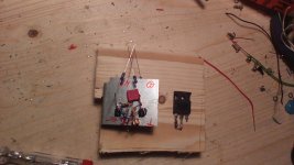
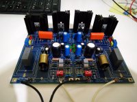
Input stage CCS tests
By the way, on another more general FSP topic now, there was discussion by me a couple of times in the past about what actual noise penalty an active CCS would have brought vs the standard R13 passive CCS and how it would have helped for the K369s drift in MC builds where the source resistors are very low value so the input stage's thermals are wilder.
Well, given the opportunity I was examining a local fellow's rather hit or miss for active parts selection modest FSP attempt, I decided to also test CCS options while reworking it. So I made two mini CCS perfboards for substituting R13 and measure. One has DN2540 depletion mode Mosfet, the other has BC560C cascode and BC327-40 Zener mode ref BJTs. In other words one like those plate CCS we often see in tube amps input stages and another like the Gingertube's Baby Huey input stage current sink but reversed to a source.
I had trimmers in the current sources so by adjusting their current to the folded cascode stage I could change the TP1-TP2 test voltage alike when changing the rail voltage with the FSP's VR2x trimmer when having the R13.
The Mosfet source controlled the TP1-TP2 voltage drift best but gave 6-7dB rise on the noise floor. On the other hand, results with the particular BJT source were erratic. Sometimes it would give the same added noise as the Mosfet's but with worse TP1-TP2 drift, another time the noise would jump too high. The K369s should have been setting off to spurious oscillation due to the small BJT cascode CCS's much wider bandwidth.
Anyway I would have possibly accepted up to 3dB more hiss from the extra active components current noise injection, if with medium sensitivity loudspeakers, but not 6-7dB so R13 is better left to where it is. I did not see THD improvement either when using a CCS. Because the signal swing there is tiny, a higher impedance source than R13 did not matter to better distortion.
I could have argued about better rail noise rejection at least but when I measured the FSP shunt reg's output rail from power off to power on through capacitor coupling to FFT analysis nothing changed from what residual it could display. The same -145dB audio card's grass 10kHz baseline and the same hum spikes that the test cables alone picked up when power was off. So no real ripple or random hiss problems to reject from the B+ line in this. Its all about building with good shielding, careful wiring, and correct grounding, for best harmonic noise result (hum & buzz).
Attachments
Gain question
Thanks Nick
I read on the Gain section of your guide that for high MC 2-2.5mV only Q1 populated, has a R2 of 68 Ohm ? Is that correct or a typo? It's supposed to be 6.8 Ohm.
The same for ~5mV MM is R2 91 Ohm or 9.1 Ohm?
thanks again
n general we prefer no more than 50V raw DC to reach the FSP's onboard regs inputs. Large DCin-DCout drop is good for linearizing the CCS MOSFET regarding its own capacitances but after 12-15V drop its a diminishing return and we inherit a hot CCS sink situation that affects the ambient temperature delta in the box so the drifts go wilder. High raw DC input also puts Q2x to strain.
Thanks Nick
I read on the Gain section of your guide that for high MC 2-2.5mV only Q1 populated, has a R2 of 68 Ohm ? Is that correct or a typo? It's supposed to be 6.8 Ohm.
The same for ~5mV MM is R2 91 Ohm or 9.1 Ohm?
thanks again
Last edited:
Hi
Its not a typo. The 2SK369 has very high transconductance and it only takes one that also needs to be degenerated that heavily by source resistance for those higher output carts.
There are also side benefits from that. More thermally stable & even less reflected input capacitance. There is no appreciable Rs noise contribution since the coil generator's resistance in such cartridges is more than those resistors values.
- Home
- Source & Line
- Analogue Source
- Simplistic NJFET RIAA