As written before add a resistor in series.
Regards
Good advice.
As written before add a resistor in series.
Regards
Wich value?
Wich value?
At least 10 times what expected the cart is about I would say. But don't do it if a cart isn't really unknown for that info so to avoid any accidental measurement move IMO.
Yes, or 200R, or 1k even. Delta the meter to show zero first including test leads and all crocks when shorted in a loop, then measure the protection resistor attached on those crocks, note it down, then add the cart in series, measure the total, then subtract the noted value from total. That will be the cart's net value. But I inform you it will be around 18-19 Ohm within 5% between channels for your 103R. Also its weight will be 8.5 gr and its 10Hz compliance 13-14cu.
From 5dB bump you went down to 0.5dB last octave bump. Which is not much there with MM carts and their mechanical issues, they struggle beyond 15-16kHz.
Proportional to gain, the resultant bumps are basically the same.
There were MM cartridges that had extended HF response, but they are probably not available any more.
I can't recall if I have ever found this advice.
Is it safe to measure the resistance of an MM or MC coil using conventional resistance meters?
Yes.
Magnetic Phono Pickup Cartridges
Proportional to gain, the resultant bumps are basically the same.
There were MM cartridges that had extended HF response, but they are probably not available any more.
You won't need a buffer to control an MM cart's interaction in practice. You will see that with a test record on FFT. Else all MM stages would use one when its very rare. Just my experience with such systems, not trying to influence your design choices.
You won't need a buffer to control an MM cart's interaction in practice. You will see that with a test record on FFT. Else all MM stages would use one when its very rare. Just my experience with such systems, not trying to influence your design choices.
Well, just because very few use an input buffer for MM phono preamps, doesn't mean that it shouldn't be used. Most commercial designs are made at the lowest cost.
This effect is not seen with triodes, for example, but it is slightly evident with an EF86 input. I assume there is significant input capacitance on JFETs that is interacting with the inductance of the cartridge to produce a resonance, but I don't know that for a fact.
To each their own, obviously. I'd rather make something that is far and above better than anything I can buy, even if it's advantages are only evident on test records. Otherwise, I'd just buy someone's phono preamp and be done with it.
At least 10 times what expected the cart is about I would say. But don't do it if a cart isn't really unknown for that info so to avoid any accidental measurement move IMO.
Yes, or 200R, or 1k even. Delta the meter to show zero first including test leads and all crocks when shorted in a loop, then measure the protection resistor attached on those crocks, note it down, then add the cart in series, measure the total, then subtract the noted value from total. That will be the cart's net value. But I inform you it will be around 18-19 Ohm within 5% between channels for your 103R. Also its weight will be 8.5 gr and its 10Hz compliance 13-14cu.
Thank you so much Salas��
Its all about Miller. Tubes should have less total parasitic capacitance than large geometry low noise JFETs to be gain multiplied. But cascoded JFETs with Rs should control much of it. When simulating two parallel cascoded JFETs with 45dB gain and minimal Rs vs. one cascoded JFET with 25dB gain and much bigger Rs there should be less bumping with same inductive source than just proportional to gain due to half the initial parasitic and much more local feedback provided by its source resistor. So that's a check point on what the simulator shows. JFET models are usually just indicative on many parameters. SPICE has much better BJT models. In any case 1 meter of TT cable should show about 100pF. Add to that ~70pF from a configuration like in FSP's MM mode, its still staying within spec of what most MM carts manufacturers would recommend as minimum for loading. And there is the resistive load value also to can tweak favorably.Well, just because very few use an input buffer for MM phono preamps, doesn't mean that it shouldn't be used. Most commercial designs are made at the lowest cost.
This effect is not seen with triodes, for example, but it is slightly evident with an EF86 input. I assume there is significant input capacitance on JFETs that is interacting with the inductance of the cartridge to produce a resonance, but I don't know that for a fact.
To each their own, obviously. I'd rather make something that is far and above better than anything I can buy, even if it's advantages are only evident on test records. Otherwise, I'd just buy someone's phono preamp and be done with it.
My finished Folded
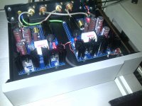
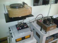
Just finished my folded implementation and couldn't wait to turn it on.
After bench testing, trim setting and stabilization, all was well and working.
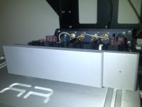
So, next step, connect it to the system, first impressions are very good, very silent (in fact dead quite), I will keep on burning it up, and do some tweaking. I just bought a Dynavector 10X5 but it will only arrive next week, then I will try and play around C2Y and so on.
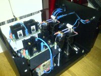
The PWS is based on 2 separate EI iron 50VA/2x18V transformers (German make and very quite mechanically), these are connected to a bridge built around IXYS rectifiers, all snubbed by an RC array. Filtering is done through 2 BHC 4.700uF each. Umbilical cord as specified on the Folded text, using Neutrik 4 pin connectors.
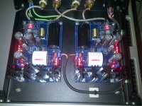
RIAA itself is built around the commonly used parts on this thread, like Mundorf, Elna, Vishay, Obbligato and Silver Mica caps, some PRP and Mills resistors + Takman Rey, and finally Vishay naked for R1 and R14.
Sorry for the poor photo quality, but had no time to take better pics.
Thanks to all involved in making this possible.
I am very happy
PS - The TT is based on Lenco platter, with PTP 5 and PTP bearing (very good), plinth is locally CNC curt and Epoxy covered and buffed by me. Tone arm is the wonderful The WAND in its latest Plus+ implementation. For now Ortofon RED2M, just waiting for the Dyna (nice its also red so my wife won't complaint)
Just finished my folded implementation and couldn't wait to turn it on.
After bench testing, trim setting and stabilization, all was well and working.
So, next step, connect it to the system, first impressions are very good, very silent (in fact dead quite), I will keep on burning it up, and do some tweaking. I just bought a Dynavector 10X5 but it will only arrive next week, then I will try and play around C2Y and so on.
The PWS is based on 2 separate EI iron 50VA/2x18V transformers (German make and very quite mechanically), these are connected to a bridge built around IXYS rectifiers, all snubbed by an RC array. Filtering is done through 2 BHC 4.700uF each. Umbilical cord as specified on the Folded text, using Neutrik 4 pin connectors.
RIAA itself is built around the commonly used parts on this thread, like Mundorf, Elna, Vishay, Obbligato and Silver Mica caps, some PRP and Mills resistors + Takman Rey, and finally Vishay naked for R1 and R14.
Sorry for the poor photo quality, but had no time to take better pics.
Thanks to all involved in making this possible.
I am very happy
PS - The TT is based on Lenco platter, with PTP 5 and PTP bearing (very good), plinth is locally CNC curt and Epoxy covered and buffed by me. Tone arm is the wonderful The WAND in its latest Plus+ implementation. For now Ortofon RED2M, just waiting for the Dyna (nice its also red so my wife won't complaint)
Attachments
Just finished my folded implementation and couldn't wait to turn it on.
After bench testing, trim setting and stabilization, all was well and working.
So, next step, connect it to the system, first impressions are very good, very silent (in fact dead quite), I will keep on burning it up, and do some tweaking. I just bought a Dynavector 10X5 but it will only arrive next week, then I will try and play around C2Y and so on.
The PWS is based on 2 separate EI iron 50VA/2x18V transformers (German make and very quite mechanically), these are connected to a bridge built around IXYS rectifiers, all snubbed by an RC array. Filtering is done through 2 BHC 4.700uF each. Umbilical cord as specified on the Folded text, using Neutrik 4 pin connectors.
RIAA itself is built around the commonly used parts on this thread, like Mundorf, Elna, Vishay, Obbligato and Silver Mica caps, some PRP and Mills resistors + Takman Rey, and finally Vishay naked for R1 and R14.
Sorry for the poor photo quality, but had no time to take better pics.
Thanks to all involved in making this possible.
I am very happy
PS - The TT is based on Lenco platter, with PTP 5 and PTP bearing (very good), plinth is locally CNC curt and Epoxy covered and buffed by me. Tone arm is the wonderful The WAND in its latest Plus+ implementation. For now Ortofon RED2M, just waiting for the Dyna (nice its also red so my wife won't complaint)
It is really, really nice.
Can you be more detailed about PSU part.
How did you snubbed it? What values? Have you used Hagerman's snubbers calculation formulas?
Hi.
Been thinking (bad sign ).
As the FS is one of my devices I'll ask here.
What if I remove the output caps from all of my devices and only have 2 at the input of my mezmerise?
This to concentrate the need of the best parts in my view to one place.
Of course different devices may do better with different output caps... Or?
Regards
Been thinking (bad sign
).As the FS is one of my devices I'll ask here.
What if I remove the output caps from all of my devices and only have 2 at the input of my mezmerise?
This to concentrate the need of the best parts in my view to one place.
Of course different devices may do better with different output caps... Or?
Regards
It has been done before in this thread in a single box preamp (phono/line buffer/active crossover?) taken a step further by substituting the phono's last stage with a switched input DCB1 stage, only coupling with 100nF from the phono's second stage drain pin. When having no pot in between. On point to point matrix board custom diy of course. Your alternative scheme is also doable. The phono section will no more stay individual and the DCB1 will be not capacitor free for any input anymore of course.
"the DCB1 will be not capacitor free for any input anymore of course"
Right, but the rest will have no caps on their outputs
Regards
In a customized & fixed full system architecture makes economical sense.
- Home
- Source & Line
- Analogue Source
- Simplistic NJFET RIAA