Yes, you are OK.Hi Salas and all !!
These are my 117s sorted by IDSS
1. 5,77
2. 5,76
3. 5,70
4. 5,41
5. 5,27
6. 5,14
7. 4,86
8. 4,79
9. 4,69
10. 3,31
I would pair them as follows.
Q7 > 1,2
Q2X > 7,8 (with R6X 33R since I'm close to 5 ma)
Q3X > 3,4 (with R3X 6K2 since I'm over 5 ma)
Q5X > 5,6
am I right ?")
Hi salas and others.
Changing the load resistors didn't make more than a minute difference - I have to listen more and switch between 47K and 220R to be certain.
I have used 100R, 220R, 470R, 1K and 47K. I settled at 220R per your advise for 103r.
The brand of the resistors have a noticeable larger impact on SQ though, hence the next question:
What about impedance and capacitance? What figures do you have for the folded both att input and output?
Regards
The output has a low about 50R source resistance, ~the K10BL RDS, bcs its a CCSed buffer. The input shows whatever load resistor you choose plus the Ciss of the 369(s) bcs there is almost no Cmiller due to cascoding. Small input+TT cable capacitance is not bothering low source resistance and inductance as the MC carts have.
Such good mechanical level TT and arm rotates and traces smoothly so the tip mass to vinyl resonance gets less excited and the load damping plays less role, that is why you don't feel much difference than level. They have obviously designed TT, arm, & cart as a coherent system for general resonance control. You have seen my humble Denon how controlled it got at last HF octave after the arm got upgraded etc. It was somewhat peaky before, more Q. First clue of good HF control on smooth TT systems is low surface noise. Imagine better control on yours which is designed and built as an F1 car. But setup has to be painstakingly immaculate, the more perfect the more demanding, exactly like in racing cars.
I agree with you about its design and revolutionary concepts. It has very attractive look and produce very nice sound. I got it from some guy lived in San Francisco who was in hurry to sale it due to his immediate relocation to South America. I do not remember the exact $, but I think it was like $1600 include everything, beside protractor. He just lost it. So, I got protractor from WB directly. The only thing I found wrong is just counterweight line o-rings. So, I got this from BW too. $1.5 a piece and I use 2.
About the adjustment. It is a pailful and time consuming process. No any type of indicators beside VTA mark on it. So, you need scales, protractor, blanket LP, and small thin mirror for the azimuth. Last time it took me just about 2-3 hours to set it up. BTW, I enjoyed the process in certain way...
.However, it has one major disadvantage: no protection cover and its collect dust like crazy.
I thought to order some custom-made cover, but I did not see any attractive design there yet. I see just square aquarium like covers.
Matching episode X season Y
Fet matching is ending...
I have 2 questions
1. Weather changed and 369s readings have changed (i'm not kidding.. ). Now I have the following IDSSs
12,33
12,53
12,41
12,46
Should I keep the 6R8 for Rs ?
Nick, is there any rule of thumb selecting the Rs when we have intermediate values ? It will save the time to measure the 9ma expected bias afterwards.
2. My Q5s have 7.8 ma IDSS. I have a lot of 170s to pair them (Q6) with IDSS from 8 to 10 ma. What range is more appropriate ?
Fet matching is ending...
I have 2 questions
1. Weather changed and 369s readings have changed (i'm not kidding..
). Now I have the following IDSSs12,33
12,53
12,41
12,46
Should I keep the 6R8 for Rs ?
Nick, is there any rule of thumb selecting the Rs when we have intermediate values ? It will save the time to measure the 9ma expected bias afterwards.
2. My Q5s have 7.8 ma IDSS. I have a lot of 170s to pair them (Q6) with IDSS from 8 to 10 ma. What range is more appropriate ?
I know you are not kidding. The room temperature changed. High gain large geometry JFETs are very sensitive. That is why I have alerted Tea early before he offered them matched to only measure them in batches when his den has about same ambient conditions between days. You stay at 6R8.
For intermediate values go with the next higher Rs when they are +0.25mA or more from lower one IDSS tier. Safer, more controlled, you could only lose some negligible amount of gain in the MC versions.
For Q6 when you have 7.8mA Q5, any higher IDSS than that will do. I would say you use your most common IDSS to find in your stash so not to dedicate difficult to chance again pairs.
*The JFETs are not done by direct lithography, they are buried under the silicone surface and diffusion is used, less defined process hence the wide range, but they can benefit from lower noise also as they stay away from surface impurities.
You stay at 6R8.For intermediate values go with the next higher Rs when they are +0.25mA or more from lower one IDSS tier. Safer, more controlled, you could only lose some negligible amount of gain in the MC versions.
For Q6 when you have 7.8mA Q5, any higher IDSS than that will do. I would say you use your most common IDSS to find in your stash so not to dedicate difficult to chance again pairs.
*The JFETs are not done by direct lithography, they are buried under the silicone surface and diffusion is used, less defined process hence the wide range, but they can benefit from lower noise also as they stay away from surface impurities.

Compare the jFETs as a Thermally coupled LTP pair.
Keep one as REF all the other become DUT.
When you find two that have a similar comparison result set them aside. keep going until you have them all batched.
Now pick out the pairs you set aside.
Put them into the Thermally coupled LTP jig and find out just how close your comparison was.
Comparison is a VERY powerful tool. Find ways to use that tool to your advantage.
eg the hamon divider.
http://conradhoffman.com/HamonResistor.html
you end up with a very accurate 10:1 ratio using comparison techniques. and then can extend that to 100:1 and 1000:1
Last edited:
Thanks Salas and Andrew !!
Fets matching finished..
Now about the leds. I'm not sure if the 1% mentioned in the guide refers to the matching between channels or the tolerance of the 7.75 voltage target. That said, is a reading of 7.65V acceptable ?
Between channels. 7.65V is alright.
Boxing day...
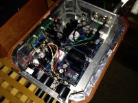
Working on boxing the amp now. PS is ready. A bit tight - I know.
What about ventilation? I believe I need a few more holes on the side with heatsinks but what is enough - to much would probably stir the 369's among other things and not enough would overheat - shorten life expectancy and so forth.
What would be a good stable temperature in the box?
Regards
An externally hosted image should be here but it was not working when we last tested it.
An externally hosted image should be here but it was not working when we last tested it.
Last edited:
Looking good, time to fire up?.
Quan
Hi quan.
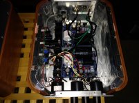
No, need to do the wiring first
. I'm still waiting for miniohms from rhopoint so there will be some more soldering before it is finished.I probably need to drill some more holes in the box too.
Yours is ready and keeping you happy?
Regards
Working on boxing the amp now. PS is ready. A bit tight - I know.
What about ventilation? I believe I need a few more holes on the side with heatsinks but what is enough - to much would probably stir the 369's among other things and not enough would overheat - shorten life expectancy and so forth.
What would be a good stable temperature in the box?
Only make it breathe best around the sinks area. You can't have stable temperature in a box if its not an actively controlled "oven", or the room isn't closely conditioned like a rack servers room, it will always be + room's ambient play. You can stick a DMM's K-Thermocouple wire inside and check the temperature rise when powered before making more holes, its a tall box and Sweden is not tropical.
Only make it breathe best around the sinks area. You can't have stable temperature in a box if its not an actively controlled "oven", or the room isn't closely conditioned like a rack servers room, it will always be + room's ambient play. You can stick a DMM's K-Thermocouple wire inside and check the temperature rise when powered before making more holes, its a tall box and Sweden is not tropical.
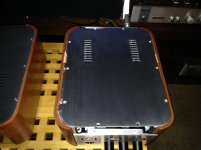
My box it tight too and has wooden sides.
Have a 5x20 mm slots (2 rows) on top and a lot of small holes on the bottom, but I'm not sure this is enough.
So, what max temperature is an acceptable on Q6 (it is the hotter one)?
How long typically need to wait till temp will stabilize?
Attachments
My box it tight too and has wooden sides.
Have a 5x20 mm slots (2 rows) on top and a lot of small holes on the bottom, but I'm not sure this is enough.
So, what max temperature is an acceptable on Q6 (it is the hotter one)?
How long typically need to wait till temp will stabilize?
Hi Alex.
I tend to remember that salas wrote a while back to keep it below 25C+ambient.
I don't know if it is typical but mine is stable after about 15min. It's based on when TP1-Tp2 gets stable near 3.6V. I have only tested this in the open so boxed might be faster than 15min.
Regards
- Home
- Source & Line
- Analogue Source
- Simplistic NJFET RIAA