Hello fellas, i am using almost the same phono stage, with some minor differences. At first, it was connected to my gainclone, after two years, i moved the gainclone to another room and put a marantz surround receiver for home theater system.
when it's in source direct mode, there is not any problems but sometimes my brother, father etc. switches it out of source direct to surround mode. when this happens, amp indicates a "peak" warning in the screen. according to user manual, this happens when the singal voltage is higer than line level standards, and can harm the dsp. so amp indicates "peak" and cuts off the signal input.
now i have to reduce this signal level coming out of m "le pacific" jfet riaa but i don't know the exact voltage of it. i could use a pot on the output but i worked too much to match its components for stereo, don't want to ruin it with a $1 pot.
i wonder if some fellas had experienced the same issue and what's their solution. how much resistance should i add to output?
thanks in advance everyone...
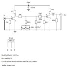
here's my shematic, (the outpuc cap is 2,2uF in my circuit)
when it's in source direct mode, there is not any problems but sometimes my brother, father etc. switches it out of source direct to surround mode. when this happens, amp indicates a "peak" warning in the screen. according to user manual, this happens when the singal voltage is higer than line level standards, and can harm the dsp. so amp indicates "peak" and cuts off the signal input.
now i have to reduce this signal level coming out of m "le pacific" jfet riaa but i don't know the exact voltage of it. i could use a pot on the output but i worked too much to match its components for stereo, don't want to ruin it with a $1 pot.
i wonder if some fellas had experienced the same issue and what's their solution. how much resistance should i add to output?
thanks in advance everyone...
here's my shematic, (the outpuc cap is 2,2uF in my circuit)
Attachments
Hello fellas, i am using almost the same phono stage, with some minor differences. At first, it was connected to my gainclone, after two years, i moved the gainclone to another room and put a marantz surround receiver for home theater system.
when it's in source direct mode, there is not any problems but sometimes my brother, father etc. switches it out of source direct to surround mode. when this happens, amp indicates a "peak" warning in the screen. according to user manual, this happens when the singal voltage is higer than line level standards, and can harm the dsp. so amp indicates "peak" and cuts off the signal input.
now i have to reduce this signal level coming out of m "le pacific" jfet riaa but i don't know the exact voltage of it. i could use a pot on the output but i worked too much to match its components for stereo, don't want to ruin it with a $1 pot.
i wonder if some fellas had experienced the same issue and what's their solution. how much resistance should i add to output?
thanks in advance everyone...
here's my shematic, (the outpuc cap is 2,2uF in my circuit)
Having 2 fet SE stages chained through passive EQ does not make it an about the same beast to a Pearl or to a Folded Simplistic. So we can't be replying why it peaks for signal by any experience from what we use in this thread. You need to analyze with a scope its output. It could be tracing down to its grounding that floats on some chance potential, its PSU or itself being susceptible to environmental or internally created noise, leaky coupling, whatever. Maybe grounding revision for itself or system wise, even shielding and/or further filtering is needed. On the other hand you maybe simply pass a level that your DSP objects by using an MM cartridge because that circuit has over 50dB gain in case it does show peak only when signal is fed to your phono. Even the 100R that lifts its EQ passing higher frequencies than strictly needed for RIAA EQ maybe allows something picked up that the DSP rejects as "level".
Salas I have 42VAC tx, can connect direct to BiB of 24V it's too much difference for the BiB? to reduce the voltage what's better a LM317 as pre-regulator to left only the 10V of difference or to add an RC to have CRC to left only 10V of difference between Vin & Vout?
If your sink takes the difference with not too much overheating better avoid extra chips. In case not, better try RC first than a chip.
Hello fellas, i am using almost the same phono stage, with some minor differences. At first, it was connected to my gainclone, after two years, i moved the gainclone to another room and put a marantz surround receiver for home theater system.
when it's in source direct mode, there is not any problems but sometimes my brother, father etc. switches it out of source direct to surround mode. when this happens, amp indicates a "peak" warning in the screen. according to user manual, this happens when the singal voltage is higer than line level standards, and can harm the dsp. so amp indicates "peak" and cuts off the signal input.
now i have to reduce this signal level coming out of m "le pacific" jfet riaa but i don't know the exact voltage of it. i could use a pot on the output but i worked too much to match its components for stereo, don't want to ruin it with a $1 pot.
i wonder if some fellas had experienced the same issue and what's their solution. how much resistance should i add to output?
thanks in advance everyone...
here's my shematic, (the outpuc cap is 2,2uF in my circuit)
You can add some resistance as Rs in second stage so you will loose some gain.... Maybe it works
")
Or maybe reducing Rd in the second stage might be even better
Anyway, maybe you should short the 100r first and see if it works with yout dsp.
Last edited:
Talking about calculators... here is Rev3 with a muh better way of determining gain.
The attached file is empty.
Thinking about folded...
Hi folks-
I've been thinking of doing the folded. Hmm, to convert my 11.02.F0 build (easier) or to build anew? I'll have to get some new r's and c's. Finding 2SK369's pre-measured in the right IDSS is proving hard. I'd rather not have to buy a batch and match-up. If anyone has a spare pair in the 9-12 mA IDSS range, I'd gladly pay for them. I will be using the 1.2R shunts I've already built.
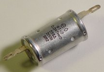
The FT-2 .047 teflons came yesterday! So at least I got that part. Small! Body is only 32mm long. I've got more than I need, so can spare a few if anyone needs them.
Cheers- Kent
Hi folks-
I've been thinking of doing the folded. Hmm, to convert my 11.02.F0 build (easier) or to build anew? I'll have to get some new r's and c's. Finding 2SK369's pre-measured in the right IDSS is proving hard. I'd rather not have to buy a batch and match-up. If anyone has a spare pair in the 9-12 mA IDSS range, I'd gladly pay for them. I will be using the 1.2R shunts I've already built.
The FT-2 .047 teflons came yesterday! So at least I got that part. Small! Body is only 32mm long. I've got more than I need, so can spare a few if anyone needs them.
Cheers- Kent
Attachments
Just convert. Its a very nice build your previous to just spare it. The proper value FT cap is nice. Looking for ~9.8mA mA bias through Q1 does not absolutely mean 11mA IDSS Q1 if you can't get hold of a couple. It may mean higher ones also with adequate increase in R2 value until you get about 9.8mA through it. A wee bit more contribution in noise by that resistor will mostly stay under the ear's radar.
At the listening level where I start hearing hum I'd be kicked out of my apartment anyway, so no real qualms there.
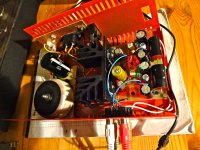
I specifically did not to use any quality parts other than the JFETs, and it's performance is absolutely good, but when I build one more properly again in the future I'll get a more spacious chassis as well.
It's a great circuit, thanks for sharing and stewarding it.
I specifically did not to use any quality parts other than the JFETs, and it's performance is absolutely good, but when I build one more properly again in the future I'll get a more spacious chassis as well.
It's a great circuit, thanks for sharing and stewarding it.
- Home
- Source & Line
- Analogue Source
- Simplistic NJFET RIAA