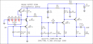
So here we have Rev2 calculator.
This one incorporates a simulator for the 1st stage of the folded cascode built with two K170 in the input.
If it passes the sieve, I can add a sheet with info for the 2SK369 buids.... just need some input on possible Idss / Vp data.
It is interesting to experiment with different Idss... if we choose an Idss higher than 8mA, the value on the trimmer becomes negative, indicating we must increase Vdd or slightly lower R13.
Attachments
It is interesting to experiment with different Idss... if we choose an Idss higher than 8mA, the value on the trimmer becomes negative, indicating we must increase Vdd or slightly lower R13.
Glad I could contribut

Am i right that the current through that branch is limited in that is proportional to the total resistance. If limited to 10ma through the branch, and youhav a jfet taking up 8-9mA, then you do not have enough left to drop a voltage across the collector of the bjt, as it is getting eaten up by the Jfets, the Jfets Rs, and the forward drop of the bjt base. Increasing the B+ voltage increases the total available current in proportion with the increase in voltage/resitance.
reading that again, it makes no sense, but i think its close

So here we have Rev2 calculator.
This one incorporates a simulator for the 1st stage of the folded cascode built with two K170 in the input.
If it passes the sieve, I can add a sheet with info for the 2SK369 buids.... just need some input on possible Idss / Vp data.
It is interesting to experiment with different Idss... if we choose an Idss higher than 8mA, the value on the trimmer becomes negative, indicating we must increase Vdd or slightly lower R13.
Should be following reality for gain quite well this revision. Try verify on your builds too.
Its nice if some of you grasp the works and can predict/tune for different biasing semis but in general for the most builders try stick to the given IDSS and B+ region as in the recommended circuits, and they will work right up.
Grasp might be a bit strong, but then again, grasping does seem to define what i do most days here, pretty well
Building my second will be strictly by the book, as it is so much easier when you follow directions. Plus, I have a feeling that you have put a lot of time into getting it ready, and that includes tweaking it to a happy medium, sound wise. The calculator by Rcruz will be a nice and handy tool . On the second build, I am adding a selector switch to be able to tune the input resistor. Easier than resoldering smd over and over again.Some DMMs are happier below 500HZ when the level is not several volts. My Fluke 17B is not reliable beyond 500Hz while my 87V is till 20KHz. The HFNRR record is testing single tone at 300Hz though. Me I use calibrated level PC FFT or my calibrated arb gen and DSO of course but with DMMs and disc if something comes up weird try factoring the procedure well. Stay at same track area and check quick enough, have good anti skating also.
All is up and running now with much better numbers with added Rs on second stage. I have most of the parts for the second build and had a question as to PSU caps. RCruz, you stated that you were surprised to notice the effect of the PSU cap selection. Would you elaborate. My brothers version has Nichicon KG. I was considering the same or similar, with the addition of a large motor run before the SSLV. Any recommendations here?
Also, how about an idea of testing the RIAA curve. I have pc Based scopes and partially functioning Tek 465
Also, how about an idea of testing the RIAA curve. I have pc Based scopes and partially functioning Tek 465
Also, how about an idea of testing the RIAA curve. I have pc Based scopes and partially functioning Tek 465
Use 1k to 10R LPAD, feed 100mV pink noise through it to your phono from your soundcard and loop it back to its line in while running any program like ARTA as spectrum analyzer on octave mode. A long EQ curve will appear that you can compare to textbooks.
Nichicon KG are good, you can start with that.All is up and running now with much better numbers with added Rs on second stage. I have most of the parts for the second build and had a question as to PSU caps. RCruz, you stated that you were surprised to notice the effect of the PSU cap selection. Would you elaborate. My brothers version has Nichicon KG. I was considering the same or similar, with the addition of a large motor run before the SSLV. Any recommendations here?
Also, how about an idea of testing the RIAA curve. I have pc Based scopes and partially functioning Tek 465
I found that everything matters but the simplistic sounds very good even with "normal" parts. My "wallis experiment" (1st folded build) uses only one TX and common psu for both channels and it sounds outstanding even with a Nuvotem 80VA tx and one Taiwan ELNA for audio 10000uf cap on the psu.
For my reference build I started with BG caps with toroids, went on through Nichicon, Mundorfs... and now settled with Jensen four poles powered by R-Core TX. (this combination in dual mono provides the best insight to the soundstage... IMO due to the better high freq operation of the Jensens)
Double mono is much better in terms of soundstage reproduction so I have it "full on".TX VA effect is quite audible also ... I am not sure the difference between R-Core and Toroids matter that much, but going from a single 80VA to a 160VA is impressive and now I have two 120VA one for each channel.... wider soundstage with much "easier" listening.
The simplistic is so good that you can benefit with every small detail.... output caps are also determinant.
It is all system dependent..... Cart load value and type can also make a BIG difference.
You must listen to it as is and then start finetunning if you need.
PS: please measure all components before you start the new build (fets, resistors and caps)... i am very interested in your opinion and I also have a "riaa calculator" to help tunning if needed.
Last edited:
Salas, or anyone. I am trying to add a selection section for the load resistor on my board and was having trouble finding the vertical pin connectors that allow you to bridge two with a square sleeve. Any ideas on a number from mouser. I don't know what they are called or how to find them.
Like this (two row). 961214-6404-AR 3M Electronic Solutions Division | Mouser
Yes it is night star. In the 19th century people were refering to the same star with two dirrefent names. Etoile du soir and etoile du matin (morining star).
I'm refering to the shematic in the wiki:
Salas Simplistic NJFET Riaa Schematics - diyAudio
Sorry for the ambiguity. Maybe i'll be more clear if I describe what I really want to do.
I'm using for now the shure m97 cartdrige and I have a bunch of 2sk170 matched at 6-6.5 ma that I want to use.
All Jfet drain pins are looking north towards B+. Good luck and let us know.
Attachments
- Home
- Source & Line
- Analogue Source
- Simplistic NJFET RIAA