these moving plate caps do indeed have air as the mojor dielectric and as such should be better than any plastic film dielectric.
But unfortunately there is some insulation between the plates, even in the metal framed variables. That will give some of the effect of the insulator dielectric.
Any idea what proportion of the total capacitance is air based cf, insulator based?
Much like the foamed teflon, or air cell in a coax. Air is the substantial medium.
Hi guys
Yeah...it wasn't really a question about specific cartridge loading...
...more about peoples experience with trimmer caps.
I said 'air-caps'...cos that's what people tend to call them.
However the high-quality Philips one mentioned...
...seems to have plates, with PTFE between them.
I have never had the chance to examine one of these trimmers...
...but judging by the price RS Components charge for them in the UK, they are probably the best made available.
Just a guess, but having something like PTFE between the plates, is possibly better than air.
My father said to me years ago, he thought traditional 'air-caps' might well 'drift' as the old big radio types did...
...due to warming & possible humidity or drying of it, between the plates.
I guess PTFE between the plates, largely stops anything like this.
As I said, not really a cartridge question...
...but the cartridge is going to most likely be a high MC, such as the Denon DL-160 or DL-110.
At some point, the tonearm & TT wiring will be re-done also.
I have been looking at some options for this...
...and see the 'Kynar' wire-wrap cable is quite popular.
Also I recently aquired a sample amount of extremely low pF cable...
...of a possibly interesting construction for lead-out cable.
This possibly won't now be used however...
...as the TT re-wire will now probably be 'semi-balanced'...
...ie. 2 wires, with overal shield ( microphone-cable ) & XLR plugs; with shield connected at one end only ( we have some exellent cable for this already, low pF, I think ).
I haven't tried the single-ended low pF cable for anything yet...
...but for anyone interested, it is Klotz 'La Grange' (AC110), intended for guitar use.
A most unusual cable for such applications I think ( studio only ), since the centre conductor is in fact solid-core.
Extremelly low pF ( I think ) of only 70pF / metre.
In a nut-shell...
...the TT re-wire may well end up being 'non-typical'...
...hence the interest of tunability.
Since there are no series signal-path connections & these devices are intended for precision adjustment, I can't see they would be any worse than DIP-switch solutions, or RCA load-plugs.
Anyhow...
...I'm just going through my parts choice quite carefully for the NJFET.
Checking out new things, I haven't used before...
...and also looking at new interesting suppliers ( ie. NOT RS Components etc. ) many of which are in China, and consequently have l o n g delivery times.
Cheers
Si.
Just another thought...
...sorry, we're always trying to 'think between the lines' on these kinda things.
The Klotz 'La Grange' (AC110) apart from having only 70pF / metre...
...also has very good, electrostatic + copper shielding...
...and an incredibly low resistance, of only 0.085 Ohms / metre.
You could say, just start with 3 metres of it...
...and just 'trim' the cable, bit by bit, to tune-in the cartridge.
Just an idea.
Cheers
Si.
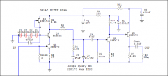
Salas, I'm using the simplistic like you designed for me but now i have some 2sk170's in my hand with Idss around 6mA. If i replace them in the circuit do i need to change some resistor values ? Also i would like to have a bit more gain to not have so much difference from CD player.
Attachments
parachuting on this thread... (having just read the main pdf file).
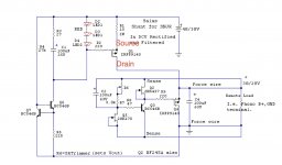
Is there any particular advantage of the higher voltage version on the original pdf file over the 24V version above (considering equivalent supplies)? I wonder if I can pick up from here (ie from the above schematics) with no disadvantage over what went on previously.
I suppose the Q1,2, and 5 must be matched for 6mA, right? Also, can I ask why the use of LEDs instead of regular diodes?
parachuting on this thread... (having just read the main pdf file).
Is there any particular advantage of the higher voltage version on the original pdf file over the 24V version above (considering equivalent supplies)? I wonder if I can pick up from here (ie from the above schematics) with no disadvantage over what went on previously.
I suppose the Q1,2, and 5 must be matched for 6mA, right? Also, can I ask why the use of LEDs instead of regular diodes?
No disadvantage, the differences in PSU voltage are dictated by the used IDSS and resulting bias currents.
Q1 and Q2 are the most demanding, Q5 can be +/-1mA, Q6 +/- 2mA. (A Q4 is a missing designation from paralleled versions, does not exist here).
Regular diodes don't give enough voltage. They would be needed to be 3x the Leds number upping the impedance of that local current sourced shunt sub supply.
Q3 is a bipolar transistor, not a Jfet. Thus it has Hfe, and needs no matching here. Just use a couple of the highest for Hfe in your stash for the phono channels.
For 18V it takes full recalculation and one thing sure is that it will not afford high enough load resistors to maintain its now gain. Expect 63dB total for the 24V Atupi one with a 1:10 SUT in front of it.
For 18V it takes full recalculation and one thing sure is that it will not afford high enough load resistors to maintain its now gain. Expect 63dB total for the 24V Atupi one with a 1:10 SUT in front of it.
They are more than enough strong for your application. Here are the modifications. You will get 5-6dB more also.
Thanks a lot Salas for customizing the schematic!
Should i change something else if i use a 0.1uf FT-3 teflon for interstage ?
")
- Home
- Source & Line
- Analogue Source
- Simplistic NJFET RIAA