THanks,,
Ill go ahead then.
The mezmerize like routing and switch system was the main pig for p2p, I am done with it at least. Phono tweak time starting from next week probably.
Attachments
 Thanks again Salas. Sorry for stalking you everywhere.
 159155
Divide your resistance then your uF into the above number and you have the 3 BD down roll off frequency. Multiply the 3 DB down frequency by 10 and that is how far the phase shift effects the frequency response.
So, 159155/1000000/.1 = 1.59 Hz x 10 = 15.9 Hz. All good, below 20 Hz
If, 159155/500000/.1 = 3.18 Hz x 10 = 31.8 Hz.
As the resistance goes down, the cap size goes up for the same roll off.
Rush
Another question on the 1Meg res value, Rush, if you don't mind.
Given the "rule of thumb" which says that Zout of one component (or gain stage) should be <1/10th - and preferably <1/20th - of the Zin of the following gain stage ... if we assume Zin for a JFET is ~15Meg then using a Gate resistor of 1Meg gets us much closer to the low-end limit than 500K does (1/15th as against 1/30th).
Is this a problem?

Thanks,
Andy
Terrific - thanks, Rush ... now I understand your choice.
What caps cost $34 for 0.1uF? I have used Relcap RTX at about $9 in this position ... I presume yours sound a lot better?
Regards,
Andy
For that with MPF103 fets one or you made a simplistic also?
For that with MPF103 fets one or you made a simplistic also?
Hi Salas - you mean the circuit using MPF102s that I posted a Q about, last year?
(You have a good memory.)No, I haven't built a Simplistic ... I have made substantial modifications to that initial circuit over the past 3 years, so that it retains the basic construct (2 x JFET gain stages with a passive composite RIAA network in between) but everything about the gain stages is different!
(Including changing to 2SK170s, to get me more gain.)Regards,
Andy
What PSU you use for it?
Salas, I'm using 2 x 12v/2.2AH SLAs per channel (which deliver a total of 26v when fully charged).
Regards,
Andy
Another question on the 1Meg res value, Rush, if you don't mind.
Given the "rule of thumb" which says that Zout of one component (or gain stage) should be <1/10th - and preferably <1/20th - of the Zin of the following gain stage ... if we assume Zin for a JFET is ~15Meg then using a Gate resistor of 1Meg gets us much closer to the low-end limit than 500K does (1/15th as against 1/30th).
Is this a problem?
Thanks,
Andy
I am not the master of JFET knowledge, I leave that up to Salas.
You can pick what ever size output cap you have or want and figure the resistor backwards within reason, 1 meg being the highest value resistor.
The roll off frequency should be less than 2 Hz.
The phono sounds the best it has after this mod, due to .... who knows why? I'm going with better coupling caps as the reason.
Rush
You can pick what ever size output cap you have or want and figure the resistor backwards within reason, 1 meg being the highest value resistor.
The roll off frequency should be less than 2 Hz.
Rush
Sure, Rush, I understand:
a) the inverse relation between resistor value and cap value, and
b) the far higher cost of good caps - so it's cheaper to use a 0.1uF cap than a 0.2uF cap!
I was simply wondering if 1Meg was pushing it a bit high!
I am not the master of JFET knowledge, I leave that up to Salas.
So, Salas ... can you advise?
Q1: Is it a problem to use a 1Meg resistor on the Gate of a JFET?
Q2: Would it be better to use 500K?
Thanks a lot,
Andy
Depends on Jfet type and its gate leakage current spec IGXS-VDS. The way we bias them in the simplistic they won't leak more than 100pA, so no problems with up to one meg. I had cranked them up further even and could not see any sudden rise for noise floor in FFT.
Thanks, Salas,
JFET is Toshiba 2SK170GR with Idss 5-6.5 ma.
Regards,
Andy
Hi John- Please feel free to emulate away!
How does it sound? Great! I only have a Mitsubishi Integra preamp to compare it to. My Salas RIAA build has more dynamics and life. Very happy with it's sound. Of course there are many variables and subjectivity. I'm also using a lab supply to power the shunts as I've been too distracted/busy to build a transformer/CLC power supply.
It doesn't have quite as much gain as the Integra but plenty loud enough. Possibly the latest ideas on this thread will address that. Still good to go. I hope I can get into in a box for Burning Amp in October!
-Kent
Sorry for some reason I missed seeing your reply Kent. Very encouraging to hear about your results. I'm still getting the parts together, but hope to start building next month sometime
Glad it's being enjoyed - does seem to be a universally well-liked and highly praised design. I'm really looking forward to giving it a whirl.
John.
hmmmmm
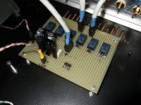
Do I understand it right? The line pre is a combination of mezmerize switching control, with some part of b1 and a 6v6 buffer?
That pic is from the mate's line pre. I put single supply b1 in the ones we are going to check out already, a couple of 1uF simple supreme caps I got, the pot to the 6v6 buffer is 50k, no need I go symmetric supply and dcb1.
Do I understand it right? The line pre is a combination of mezmerize switching control, with some part of b1 and a 6v6 buffer?
No, the second line comment is about the experimental phono. The little line amp will be with some gain, simple symmetric Fet John Curl style cheap to make solution. I had given him a B1 from mid summer now not to be without music, but he has to have some gain, his ARC amp needs that even from a CDP as source.
Now with a much better matched k170 at 8mA idss, I get 12v sharp on the output of the cascode.
Using 1k4 to power the buffer (also with 8mA fets) I get 23.7v for Vd on the top fet....
Wondefull... Allready have one board populated... soon to be news about experimental wallis simplistic
Using 1k4 to power the buffer (also with 8mA fets) I get 23.7v for Vd on the top fet....
Wondefull... Allready have one board populated... soon to be news about experimental wallis simplistic
- Home
- Source & Line
- Analogue Source
- Simplistic NJFET RIAA