OK, received the caps, Mundorf 0.1 uF Silver and oil.
Took out the direct coupled JFET, added a 0.1 uF cap with 1 meg to ground on the RIAA board. Then ran to an out board DCB1 sub board and pulled power and ground from the Mezmerize B1 Buffer. I am not fretting about large caps anymore and no hum issues, sounds fantastic.
This is a must do, actually the Mezmerize B1 Buffer board could have double set of DCB1s before and after the volume as I have essentially done and it wouldn't hurt. Four JFETs are a lot cheaper than high quality, large value, coupling caps.
Thank you Salas,
Wonderful stuff!
Rush
Hi Rush
Can you post a schematic of what you have now.... very interested I am.
The fets came from reichelt they have a Fbb42 printed... Fairchild ?... Measured 17mA idss....I am using a TENMA 72-7930
Its 0.8% +1 count for DC mA which is decent. One 0.5% +10 count meter I got was still showing shy by 0.2mA to my best 0.15% meter for BL. So it must be IDSS and meters.
If you see a tiny f somewhere not in in part number line on your 245's face its FAIRCHILD.
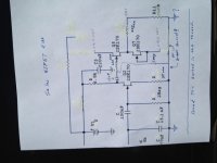
DCB1 added to output
Yes, here is an earlier schematic that shows the output of the cap (0.1 uF) and 1 meg to ground (just the output is the part I used, not the RIAA from this early one) and the schematic I chopped up posted earlier. Also, the ground for the DCB1 is to the Mezmerize board.
Rush
Hi Rush
Can you post a schematic of what you have now.... very interested I am.
Yes, here is an earlier schematic that shows the output of the cap (0.1 uF) and 1 meg to ground (just the output is the part I used, not the RIAA from this early one) and the schematic I chopped up posted earlier. Also, the ground for the DCB1 is to the Mezmerize board.
Rush
Attachments
Last edited:
I just happen to have that very thing. Any change or diminishing ofsound, or did you get to listen, pre DCB1?
It is better. Better sound stage, smoother. Still trying to find time to listen more. Only have 2 hours of low level listening now.
Rush
Yes, here is an earlier schematic that shows the output of the cap (0.1 uF) and 1 meg to ground ...
Rush
Hi Rush,
Can you tell me why you went for a 1Mohm res off the 2nd JFET Gate ... rather than, say, half that? IE. what advantage does 1Meg have here, compared to 500K?
Thanks,
Hi Rush,
Can you tell me why you went for a 1Mohm res off the 2nd JFET Gate ... rather than, say, half that? IE. what advantage does 1Meg have here, compared to 500K?
Thanks,
159155
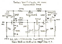
Divide your resistance then your uF into the above number and you have the 3 BD down roll off frequency. Multiply the 3 DB down frequency by 10 and that is how far the phase shift effects the frequency response.
So, 159155/1000000/.1 = 1.59 Hz x 10 = 15.9 Hz. All good, below 20 Hz
If, 159155/500000/.1 = 3.18 Hz x 10 = 31.8 Hz.
As the resistance goes down, the cap size goes up for the same roll off.
In the original circuit we had 2.2 uF and 1 meg, but I am using a DCB1 buffer with a 25k volume pot and a 220k input resistor. So an effective 22k resistance following the output cap.
The math, 159155/22000/2.2 = 3.29 Hz x 10 = 32.9 Hz phase shift
Really need to double the output cap, now that is getting pricey.
I see no advantage of using a lower resistance into a B1 buffer and I see great reasons to use the smallest cap that will do the job. The 0.1 uF coupling cap I used are $34 each, if I was looking a 4.7 uF of the same quality, would be $111 each and who knows if the bigger cap would sound as good as the smaller one, some folks would by pass the 4.7 uF with a smaller value and the cost keep going up.
I also don't have the physical space in my preamp for a larger cap anyway.
Rush
159155
Divide your resistance then your uF into the above number and you have the 3 BD down roll off frequency. Multiply the 3 DB down frequency by 10 and that is how far the phase shift effects the frequency response.
So, 159155/1000000/.1 = 1.59 Hz x 10 = 15.9 Hz. All good, below 20 Hz
If, 159155/500000/.1 = 3.18 Hz x 10 = 31.8 Hz.
As the resistance goes down, the cap size goes up for the same roll off.
In the original circuit we had 2.2 uF and 1 meg, but I am using a DCB1 buffer with a 25k volume pot and a 220k input resistor. So an effective 22k resistance following the output cap.
The math, 159155/22000/2.2 = 3.29 Hz x 10 = 32.9 Hz phase shift
Really need to double the output cap, now that is getting pricey.
I see no advantage of using a lower resistance into a B1 buffer and I see great reasons to use the smallest cap that will do the job. The 0.1 uF coupling cap I used are $34 each, if I was looking a 4.7 uF of the same quality, would be $111 each and who knows if the bigger cap would sound as good as the smaller one, some folks would by pass the 4.7 uF with a smaller value and the cost keep going up.
I also don't have the physical space in my preamp for a larger cap anyway.
Rush
Terrific - thanks, Rush ... now I understand your choice.
")
What caps cost $34 for 0.1uF? I have used Relcap RTX at about $9 in this position ... I presume yours sound a lot better?
Regards,
Andy
Terrific - thanks, Rush ... now I understand your choice.
What caps cost $34 for 0.1uF? I have used Relcap RTX at about $9 in this position ... I presume yours sound a lot better?
Regards,
Andy
I am using Mundorf Silver and oil. They do sound good. Next step up is the V-Cap FTFT for $122 / pair. I also put the Mundorf 0.1 inside the RiAA circuit so I got twice the pop and twice the spend. It never ends.
Rush
I am using Mundorf Silver and oil. They do sound good. Next step up is the V-Cap FTFT for $122 / pair. I also put the Mundorf 0.1 inside the RiAA circuit so I got twice the pop and twice the spend. It never ends.
Rush
159155
Divide your resistance then your uF into the above number and you have the 3 BD down roll off frequency. Multiply the 3 DB down frequency by 10 and that is how far the phase shift effects the frequency response.
So, 159155/1000000/.1 = 1.59 Hz x 10 = 15.9 Hz. All good, below 20 Hz
If, 159155/500000/.1 = 3.18 Hz x 10 = 31.8 Hz.
As the resistance goes down, the cap size goes up for the same roll off.
In the original circuit we had 2.2 uF and 1 meg, but I am using a DCB1 buffer with a 25k volume pot and a 220k input resistor. So an effective 22k resistance following the output cap.
The math, 159155/22000/2.2 = 3.29 Hz x 10 = 32.9 Hz phase shift
Really need to double the output cap, now that is getting pricey.
I see no advantage of using a lower resistance into a B1 buffer and I see great reasons to use the smallest cap that will do the job. The 0.1 uF coupling cap I used are $34 each, if I was looking a 4.7 uF of the same quality, would be $111 each and who knows if the bigger cap would sound as good as the smaller one, some folks would by pass the 4.7 uF with a smaller value and the cost keep going up.
I also don't have the physical space in my preamp for a larger cap anyway.
Rush
So you are loading the simplistic second stage directly with a 25k pot...
Maybe the cure would be another dcb1 buffer between the simplistic and the pot right ?
Last edited:
......
Maybe the cure would be another dcb1 buffer between the simplistic and the pot right ?
Thats what I did, DCB1 before 25k pot.
Rush
RC, its simple what I proposed to Rush back then so to save money and gain quality on boutique coupling. What we make here is full phono systems interfacing to many line pre-amps right? So they got a buffer stage and 2.2uF or more output capacitor. But Rush already had it integrated in a box with dcb1 circuits, a JFET active crossover filter, and minus polarity shunt reg available. So I told him, look don't spend top dollar for higher capacity couplers, utilize your dcb1 in place of the phono buffer. To do that he had to couple further back at second stage's load resistor node to dcb1 circuit using high input resistance. So 0.1uF was enough, cheaper, smaller, and arguably better due to less foil. No he could not stick the vol pot there of course, but he sandwiched it between two buffers. Still same buffers count bcs he eliminated one integral to the phono. Clear?
- Home
- Source & Line
- Analogue Source
- Simplistic NJFET RIAA