Now another point: Why did you choose 47nF for interstage ? Can I use 100n ?
In the output... is 4u7 too much ?
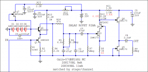
Because for 47nF is getting even same cap as Riaa's one to do less part types sourcing, and VLF roll off is better predetermined for output cap and line preamp random combinations. What is the input impedance of your preamp?
See also how RIAA when looked very up close turns with the above C3,4 values to 10K DCB1 when 2M2 R6. R9 1M is only a termination against C4 referring to nowhere to avoid pops. With real life impedance of usual line preamp 10K to 100K maybe you want to see again about your initial 1M4 choice of R6 for voicing.
Attachments
")
Salas,
You are the man.
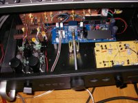
I finished the first two parts of my phono pre amp. I am tickled, it sounds great!
I used your Regular MC schematic (56db). I used your SSLV1.1 regulators (one for L & one for R) with a pot to adjust voltage to get a 38V rail. And I have your B1 (Mesmerize) as the source selector.
It has plenty of gain for a F5 amp and 90 + db speakers.
The last part is my 24db per octave 2 way electronic crossover using B1 type buffers between sections. This board is stuffed.
I will use 2 Hypnotize (L & R) boards to power the buffers (8 B1's per channel).
But I haven't stuffed the Hypnotize boards yet.
I had asked about grounding in another thread. So I will mention there isn't any hum (at least not yet). I used a separate box for the 2 transformers (needed 2 different voltages) and used a 4 wire speaker cable to bring the DC voltage in.
That is one ground, +16vdc, -16vdc, +50vdc.
I wasn't sure how this would work, but it does work, so far.
I brought the ground to a central point on a PC board that I also used for the input and output RCAs. Then the Mesmerize has one ground from the in put to the power supply, all the input and outputs to the Mesmerize are 2 wire (L & R), no ground connection. The phono has the input RCAs floating and the only ground is from the central point to the input ground to the shunt regulators.
I thank you for all the help,
Rush
You are the man.
I finished the first two parts of my phono pre amp. I am tickled, it sounds great!
I used your Regular MC schematic (56db). I used your SSLV1.1 regulators (one for L & one for R) with a pot to adjust voltage to get a 38V rail. And I have your B1 (Mesmerize) as the source selector.
It has plenty of gain for a F5 amp and 90 + db speakers.
The last part is my 24db per octave 2 way electronic crossover using B1 type buffers between sections. This board is stuffed.
I will use 2 Hypnotize (L & R) boards to power the buffers (8 B1's per channel).
But I haven't stuffed the Hypnotize boards yet.
I had asked about grounding in another thread. So I will mention there isn't any hum (at least not yet). I used a separate box for the 2 transformers (needed 2 different voltages) and used a 4 wire speaker cable to bring the DC voltage in.
That is one ground, +16vdc, -16vdc, +50vdc.
I wasn't sure how this would work, but it does work, so far.
I brought the ground to a central point on a PC board that I also used for the input and output RCAs. Then the Mesmerize has one ground from the in put to the power supply, all the input and outputs to the Mesmerize are 2 wire (L & R), no ground connection. The phono has the input RCAs floating and the only ground is from the central point to the input ground to the shunt regulators.
I thank you for all the help,
Rush
Attachments
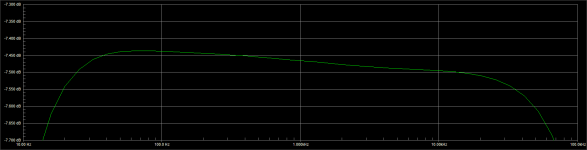
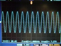
I was doing some phono related stuff too. Was checking the bias for the experimental ones. I put the two stages together with the Riaa in between. Not too bad the sim models, they only showed 1V more load drop in the second stage. Gain was spot on. So I trimmed the values around it a bit to center the buffer best. It gave ~20 Volt peak to peak before compression started kicking in. I have noted the practical values in red, should be the same for all such example schematics discussed, they share the same second stage and B+. If choosing 7.5mA Idss Q5 & Q6, R11 can be 1.5K. Q3 can be a bit slack for exact Idss choice due to enough degeneration from R8 that takes it near 3.5mA. Looking for ~23V drop across R10 should be that stage's channel matching criterion.
Attachments
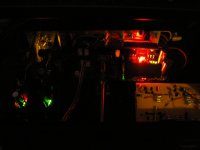
Ooops! Another one baby. Look at those lights! Very nice job that you won hum in this combo. Plus you say you like it, so only remains I wish many nice & relaxing vinyl sessions.
P.S. What TT, cart, speakers?
I have two sets of speakers both Snell E and E2. The E is bi-amped with a slightly modified Rane AC22, a pair of stereo F5s the E2 has standard internal crossover. I guess I like the Snell E speakers.
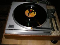
The Turntable is a Technics SP10 II in a custom plinth made out of a mixture of kitty liter and isophthalic resin poured into a hardwood frame (to make it pretty) and an Eminent Technology ET2 air bearing arm and a Lyra Delos cartridge. The arm is wired with Van den Hul silver 150 micron.
The audio wire I used in the pre amp is also Van den Hul 300 micron silver.
Here is a photo of the turntable/arm/cartridge.
Rush
Attachments
What other phono pre you used for the Delos?
The Delos is new, it replaced an 20 year old Van den Hul MC10.
I was using 2 different tube pre amps. A Counter Point SA-7 most recently and a home designed and built DIY rig built years ago. I borrowed pieces from all around and sliced them together. Made a nice sounding pre amp for 15 years. It uses 7308 phono tubes with a ccs (k389 I think), 6FQ7 line amp.
I also have a Audio Research SP6 modified with a new soft start stable power supply. Haven't listened to that in years.
The Counter Point I pulled out of storage when I detected some distortion in the home built unit and realized I couldn't find the schematic.
That's what started me on the quest for a better RIAA phono. And it just grew and grew. Now the pre amp box will be full, so that will be that when the Hypnotize boards are stuffed and the cover can go on the pre amp for good. (For good?)
This RIAA phono is very quiet compared to the tubes. Everything is Crystal clear, wide image, no harshness. I like it.
Rush
Should be down to circa 50pF remaining Miller and all at ~3Vds cascoded I measured at that bias and degeneration, but I don't trust the Jfet spice models to such a degree for giving the absolute HF response especially in the presence of a Riaa filter. We will have to normally build it, measure it and listen to it, then tweak it if necessary. I will FFT measure on the breadboard model but there are extra capacitance and inductance parasitic elements so not to fully rely.
- Home
- Source & Line
- Analogue Source
- Simplistic NJFET RIAA