In the Simplistic first stage, Salas bias the cascode bjt at around 8v so we get 7.9V for Vd in the lower k170.
You get Vb-Vbe for Vd. In the folded you will get Vb+Vbe.
I was refering to this info (fig 7) lab pageYou get Vb-Vbe for Vd. In the folded you will get Vb+Vbe.
Thank you for the tip on the folded cascode... So in the case of your last schematic http://www.diyaudio.com/forums/analogue-source/129126-simplistic-njfet-riaa-790.html#post3141205
we get Vd = Vb+Vbe right ?
we get Vd = Vb+Vbe right ?
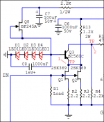
Practical considerations for 1st stage folded
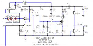
Having done some experiments on how to build the folded first stage easy due to there is a delicate enough balance between biasing parameters like different Vf Leds or a bit different K369 Idss & Vgs, resistors tolerances, Vbe of the cascoding transistor, I think that the best is to have a way to trim R13. The goal is to can center the TP2 voltage respective to GND at half the value of TP1 to GND for both channels. Its a control to match the gain also. That could be a 1K 2W resistor with a 500R 0.5W (Bourns 3296) in series than a fixed 1.2K 2W, or a an extra position in parallel so to use double 1W resistors experimenting, or a series resistor position for adding on 1K around to 1K2 total, whatever. I could do the bias I wanted by varying several other things but naah too complicated for a guide. R13 lends itself best. The thingy when checked with just one K369 matched the sim expectation giving 100 times gain by the way. It swings up to LedsVf+Q3Vbe. I took it up to 8V TP1 and it swings it full Peak-Peak clean. It ain't noisy also, considering the open test set up and the gain.
Having done some experiments on how to build the folded first stage easy due to there is a delicate enough balance between biasing parameters like different Vf Leds or a bit different K369 Idss & Vgs, resistors tolerances, Vbe of the cascoding transistor, I think that the best is to have a way to trim R13. The goal is to can center the TP2 voltage respective to GND at half the value of TP1 to GND for both channels. Its a control to match the gain also. That could be a 1K 2W resistor with a 500R 0.5W (Bourns 3296) in series than a fixed 1.2K 2W, or a an extra position in parallel so to use double 1W resistors experimenting, or a series resistor position for adding on 1K around to 1K2 total, whatever. I could do the bias I wanted by varying several other things but naah too complicated for a guide. R13 lends itself best. The thingy when checked with just one K369 matched the sim expectation giving 100 times gain by the way. It swings up to LedsVf+Q3Vbe. I took it up to 8V TP1 and it swings it full Peak-Peak clean. It ain't noisy also, considering the open test set up and the gain.
Attachments
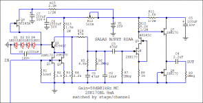
Now that I thought of it, why not a single 369 for 0.5mV carts, 63dB was for LMC, 57dB is MC classic. Less input capacitance more headroom for MC. And it dawned on me, since varying the PSU can have analogous effect like varying R13 why not use a trimmer for R12 instead that shows less drop and less mW ta-da!
Attachments
K369 for noise is as using 2 K170 roughly. Yfs and Ciss go up together, so no free lunch, it shows some advantage in lower frequencies for a special kind of noise named generation recombination as Scott W. explained. Here you are, another toy attached.")
Attachments
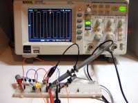
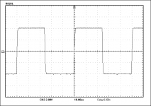
Meantime the folded thingy goes for 8 hours without moving bias or gain. I think it passes as a gain cell to be evaluated. Not bad 20kHz square wave for a high capacitance JFET and 50 Ohm source also. Carts will be lower Zo. There is the cascoding BJT, but no loop feedback, or substantial local to speak of, plus 40dB gain and all that remaining Crss Miller Jazz. -3dB is @ 500kHz BTW.
Attachments
The telescopic cascodes in the standard PDF guide configs had 3.3K or 2K4 load resistors, i.e. even bigger. The difference will be the BJT's bias current which has to be lower here and the slew when charging the same value filter capacitors. Does not give any limitation hint in the sim, but no mod will go universally recommended if not built in full phono by hands and approved by ear(s) first.
- Home
- Source & Line
- Analogue Source
- Simplistic NJFET RIAA