You had enough VDCin to spare it seems. That created extra heat. To have the error amp BJT (Q3) crippled its either over voltage or a discharge from the Vref filter cap. It can take the Vref CCS JFET out (Q5) sometimes too. Your debugging went smooth though. Is it any better for hum now you got the power brick and it can be located away from the signal box?
the distance between the ps(power brick) it`s 1.5 meters.i can`t make a comparison right now because my preamp case is at ''cosmetics'' ") .the last laqueur layer(totally 5 layers) it`s applied and i left it at my friend.
.the last laqueur layer(totally 5 layers) it`s applied and i left it at my friend.
when i done the first tests the shunt it was broke and the test were made with it so...i didn`t knot it doesn`t work.
now it still has little hum but in comparison to the first time it`s lower.now i`m waiting for the case and i want to buy some copper sheet because i read somewhere the aluminium doesn`t help at all with the screening of the case.
i`ll try tomorrow the old ps(classical transformer) to see what diferences are between the old and new one
want to ask you something more what is the minimum voltage drop across regulator for this to work at his best?
.the last laqueur layer(totally 5 layers) it`s applied and i left it at my friend.when i done the first tests the shunt it was broke and the test were made with it so...i didn`t knot it doesn`t work.
now it still has little hum but in comparison to the first time it`s lower.now i`m waiting for the case and i want to buy some copper sheet because i read somewhere the aluminium doesn`t help at all with the screening of the case.
i`ll try tomorrow the old ps(classical transformer) to see what diferences are between the old and new one
want to ask you something more
what is the minimum voltage drop across regulator for this to work at his best?and you suggest i should decrease the value of r(22r) from my crc and increase r1 for current limit to 100-110ma so i could reach a higher drop across the regulator?
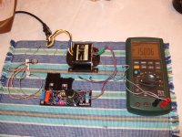
with r(crc) 1r i have : 31.5(output voltage after crc filter) - 24(output voltage after shunt regulator)=7.6(voltage drop on shunt regulator)
this is more appropriate to what you recommend.
guess tomorrow i`ll try this too
with r(crc) 1r i have : 31.5(output voltage after crc filter) - 24(output voltage after shunt regulator)=7.6(voltage drop on shunt regulator)
this is more appropriate to what you recommend.
guess tomorrow i`ll try this too
Last edited:
I would like you to have 5V drop across regulator minimal and 150mA current. Because each of your channels eats 25mA it will be nice to have 100mA to massage the Mosfets a little better than the spare 50-60mA you now got down to. If the radiator will not go more than 45-48C that is. Since its a small one you said.
finished tweaking the ps.with a curent draw of 165ma and 5v drop across it the radiator for the mosfets burns at 70C.what do you say...should i search for an 1-2mm aluminium sheet so i can do for it a bigger radiator?
but for today i`m finished.in my country it`s a Christian holiday and i don`t work these days my mom just told me...cause i didn`t knew.well it`s good tomorrow it`s another day.will get my case too ...can`t wait for some more tests.
but for today i`m finished.in my country it`s a Christian holiday and i don`t work these days
my mom just told me...cause i didn`t knew.well it`s good tomorrow it`s another day.will get my case too ...can`t wait for some more tests.How small the radiator is? Dimensions? Rising easily in temp. Yes reinforce it or get a bigger one. Its good to keep those drop and current settings if you can but with logical heat. Else, the heat will compromise the reg's reliability. Incidentally I was experimenting on regulator prototype board too today.
Attachments
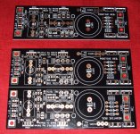
Wow! The new V1.1 man-in-blk, blk-it's-back or whatsoever!
Value of the o/p orange Philips MTK? Can't read.
Vref made of two leds, trimpot + fixed R, I guess.... Can't see the latter anyway.
Will sport a configurable Vref to each one's desire. Can take trimmer, fixed resistor(s), Zener, Leds. Very stable with film 4u7+R Zobel output termination on first tests. Also uses different Toshiba low noise JFETs. Nice little drift with those for just adj. resistive + 2 Leds Vref. Has more open OLG than previously also. Unsure if I could see any noise on the scope. Very average scope though. Higher voltage and symmetric tests still to run. Tea is on those, he has a couple of projects that they tie with. Massimo, see better. PCB quality tests good. Soldered very smoothly.
Attachments
Not yet, since I will have to know it passes all tests, different Jfets reliable, and decide all components values. Topologically is V1 family, still more ironed out, film cap stable, can hot rod, take MURs. I will make a full instructions PDF when I will feel its sea worthy.
Oh man, a press leak.
Now I am on the hook. I am an excellent proto builder, since I don't read instructions well. I swap out parts at random, leave area full of metal to stimulate shorts, and generally act like a blind carpenter. The parts list so far is easier on wallet than hypno blue, and more rugged of a board than the old black hypnos. (which I still get request for)
Probably with this leak, someone else will be selling a version of it before it's 'sea-worthy'.
 ...Takes AC gives DC after all.
Yeah looks really nice
Awesome looking boards !!!
very nice boards
Looks amazing Salas!
It took weeks of consulting with CRT... Thanking him for his patience on the many changes I was asking. Needed a good layout to further work on the extended OLG and phase performance and added features. Keeps a narrow sense loop also. Will see how it goes on with the tests.
I just could not get Quanghao to adopt that, no matter how hard I tried.Keeps a narrow sense loop also.
Tea is on those, he has a couple of projects that they tie with.
Now he should tell us a bit more what is cooking, or, better, boiling before adding his preferred tea-bag
- Home
- Source & Line
- Analogue Source
- Simplistic NJFET RIAA