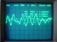
Left gate stopper at 60R and bypassed base stopper on bc550(Q8) slight gain in magnitude same freq. Now 140mVpp and 45mVrms.
Would like to put gate and base stopper back to original and increase base stopper on Q3 which is the bc546B.
My reasoning is that with the increasing maginitude of oscillation when we reduce the stopper values further up the chain it means the oscillation is before that part. If is was that part we would see a drastic change or no change.
Last edited:
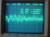
While I was pulling the 60R out, I installed 330R. Steady State oscillation has stopped. I now get periodic blips. Not a solid line by any means but a HUGE improvement. I will do the same for the error amp as well.
Note that the vertical scale is now 2mV/div
Note that the vertical scale is now 2mV/div
Attachments
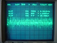
Get much of the same when moving the gnd of the probe around. Attached is the 50ns and 10us with 47R as base stopper on error amp.
I am wondering if I should move the gate stopper back to 120R on the 9140 to see if oscillation resides in error amp or shunt.
The attached look more like noise to me now.
I am wondering if I should move the gate stopper back to 120R on the 9140 to see if oscillation resides in error amp or shunt.
The attached look more like noise to me now.
Attachments
Last edited:
Ooops, it may be working OK now and the noise is not the shunt. Because periods vanished. To be sure, a test is if it has something bad it will make the phono's FFT full of harmonic grass all over. If its as clean as with the other channel on original reg its not its own noise.
P.S. Catch you later.
P.S. Catch you later.
This is 9140 with almost double Crss than 9240, and your first iteration proprietary layout, so when it works, it works with what stoppers it needs. Maybe a 220R test at a point for the sake of it. It is not the phase margin bcs both doubling the Ccomp and changing the step network's place did not change it at all, nor the termination from film Zobel to 10x value lytic did. Actually it loses margin with more base and gate stopping. Some layout inductance talked to some base and gate and it had a certain period resonance its the most probable. Watch that FFT noise floor VS other channel with V1, its tell tale on a 58dB phono. If it will feed even 1-2mV of noise, the first stage cascode will catch it. No PSRR to speak off. I wonder where the scope gets that noise when the reg is powered off though. Can it be doing something with the bench DVM which is also across the output or is there some emitting equipment near? Also does it start fast now, so there is nothing left to see about in the main CCS part? Will be nice if its fully OK and you will not have to bother with layout experiments.
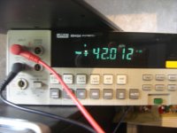
Help me explain this. That noise was read across a 5W 700R DALE wire wound resistor. If I read across a 510R 1/4 watt carbon or metal film I don't see the noise. Even with DVM attached.
The regulator picks up instantly when hooked up to the RIAA. It takes its time when hooked up to 700R resistor.
I will try 243R (since I have one) as gate stopper on other channel. If it works I will install in both channels. I ran a quick scan on the noise floor of the riaa and it was same as V1.0 (or very close). I will do a more detailed analysis later when I get my work bench cleaned up. It showed absolutley no 60,120,.... Hz peaks. I still have not gotten my measured noise floor to your levels though.
- Home
- Source & Line
- Analogue Source
- Simplistic NJFET RIAA