O.K.
Next project.
Or better: next step in this project?
Franz
Best step in this project.
Don't know, I have listened to both balanced and unbalanced components in several systems but the parameters are too many so to speak confidently. A fair thing would be to make the same CCT in both guises with same parts and live with it enough before commenting. Me I always follow economy. Due to I am not an engineer, I try to make simplest before I lose the ball so I go SE. I am pro useful, i.e. easy to make and fulfilling most of my subjective needs, not unconditionally best, I can't be sure I can design or control such anyway. J.Gerhard had made many experimental CCTs in the course of his MPP thread and maybe he can be more adequate for adding his comments on your SE VS Balanced query, if you ask there. He is good in describing subjectively too.
J. Gerhard answer: http://www.diyaudio.com/forums/analogue-source/154210-mpp-140.html#post2202746 I will go to try balanced due to the fact the rest of mine system is balanced.
Salas
I measured my 100 pieces 2SK170V with 10VDC and 100R resistor.
Result:
9-10 mA 8 pcs.
10-11 mA 25 pcs.
11-12 mA 24 pcs.
12-13 mA 18 pcs.
13-14 mA 18 pcs.
14-15 mA 7 pcs.
So, I have no chance to build the 15mA Version of this circuit.
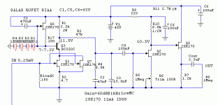
Which circuit version would you recommend to obtain 60dB gain?
I would prefer to go with 10 to 12mA, looking at the available numbers.
Franz
Hi Merlin
Are you pointing to a balanced riaa ?
Hi Rcruz
Yes, about output cap no back to Auricap: Obbligatos perform extraordinarily well togheter the Vishay.
Mine idea for balanced is one big pcb with the 4 regs. togheter the 4 Simplistic NJFET Phono RIAA & in a separate box the Tx + PSU, first approach will be using only using the same 2 Tx & 2 PSU that I'm using now & after upgrade for 4 Tx + 4 PSU.
I would prefer to go with 10 to 12mA, looking at the available numbers.
Franz
OK, for 11mA then.
Attachments
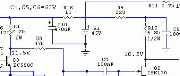
Its the way they interact with the rest. The target Lipshitz is the same. Resistor values change with different IDSS tunings and create a new total filter transfer function, so I compensate C3. For 100uF change, R9 is larger here for instance, so Q2 need not run more current to bias circa 10V, hence C5 is enough RC.
P.S. Due to tolerances of all components, C3 is advised to be trimmed by ear in each individual system by preference.
P.S. Due to tolerances of all components, C3 is advised to be trimmed by ear in each individual system by preference.
Mu-metal shield & LSK380BL
@Rcruz
Arrived the mumetal shield 196mm x 315mm back self adhesive:
I'm doubting for balanced use the 2SK170BL or the LSK389BL, I have both on hand only need the measure the Idss in the LSK389BL. If I will use 2SK170BL will be all new & I suppose that will better sharing the same pcb the regs & the phono & if I will use LSK389BL will be less work because half work done. 20pcs photo:
Humm I'm enjoying only to mind in the work & the final success.
@Rcruz
Arrived the mumetal shield 196mm x 315mm back self adhesive:
An externally hosted image should be here but it was not working when we last tested it.
I'm doubting for balanced use the 2SK170BL or the LSK389BL, I have both on hand only need the measure the Idss in the LSK389BL. If I will use 2SK170BL will be all new & I suppose that will better sharing the same pcb the regs & the phono & if I will use LSK389BL will be less work because half work done. 20pcs photo:
An externally hosted image should be here but it was not working when we last tested it.
Humm I'm enjoying only to mind in the work & the final success.
Salas
Many thanks for your 11mA IDDS / 60dB gain simulation. It is very helpful, as I dont have the simulation software and all the needed knowledge behind it.
I will follow this path now, as I have all the needed parts.
Franz
P.S.
Any recommendations for a readily available shunt regulated pcb?
Many thanks for your 11mA IDDS / 60dB gain simulation. It is very helpful, as I dont have the simulation software and all the needed knowledge behind it.
I will follow this path now, as I have all the needed parts.
Franz
P.S.
Any recommendations for a readily available shunt regulated pcb?
I started the layout of my pcb.
The complete stereo circuit:
The pcb draft (every feedback and critic is welcome)
And the raw material:
Do the FET's require heathsinking?
Franz
The complete stereo circuit:
An externally hosted image should be here but it was not working when we last tested it.
The pcb draft (every feedback and critic is welcome)
An externally hosted image should be here but it was not working when we last tested it.
And the raw material:
An externally hosted image should be here but it was not working when we last tested it.
Do the FET's require heathsinking?
Franz
I started the layout of my pcb.
The complete stereo circuit:
Franz
R1, 101 must be 1.3K. Made by 3 pieces 3K9 1W in parallel in the 15mA IDSS first circuit you asked. Its a single 2K2 2W in the 11mA circuit. R12,C9a,b Would be more useful if not feeding the whole, but reserved for first stage so it cuts interaction, the other stages have already.
Attachments
... LM317 is limited to 37V...
No - the only 37V limit is the voltage difference between Vin and Vout.
So, as long as your Vin is not more than 37V higher than your Vout (and you respect the SOA) you can use LM317 at whatever absolute voltage value you wish (people often use it in tube circuits at 250V or 300V).
what about during start up? Particularly is there is a discharged capacitor on the output.No - the only 37V limit is the voltage difference between Vin and Vout.
So, as long as your Vin is not more than 37V higher than your Vout (and you respect the SOA) you can use LM317 at whatever absolute voltage value you wish (people often use it in tube circuits at 250V or 300V).
Is there any data for the 317 subjected to transient voltage overload?
- Home
- Source & Line
- Analogue Source
- Simplistic NJFET RIAA

