His cart should be equal or higher than 2mV to listen OK actually, but the strong hum shows some problem with signal. If its not coming in wrongly, It could be originating in some stage or something's seriously wrong with GND. It needs to be traced stage by stage with 1kHz tone.
If its fed with 2mV RMS (test disc if with no GEN and low impedance output attenuator), it should give about 45mV RMS on Q3's collector, 230mV on Q2's drain, same stuff after buffer. If the buffer is under suspicion, I would tap off directly before it to feed the headphone amp via coupling cap so to check if things are healthy up to there. Oscope is better, but an AC DVM can do basic stage checks if input is fed a steady tone at 2-5mV somehow.
I would check the build very thoroughly again for being exact to the schematics and to be sure that the GND isn't strongly contaminated anyway.
My first test: with a 1000 Hz from a cd test i measured 23mV AC (with a DMM) on C Q3 (the cd output is about 250mV AC) and more than 8VAC on D Q2. The signal test come in my hedphone very high, clean and without any hum.
Here there are some pictures.
http://img259.imageshack.us/img259/1576/spa1282.jpg
http://img39.imageshack.us/img39/2282/spa1279.jpg
Here there are some pictures.
http://img259.imageshack.us/img259/1576/spa1282.jpg
http://img39.imageshack.us/img39/2282/spa1279.jpg
So you fed the MM input with 250mV RMS without 1:100 L pad attenuation, and you got 23mV on BC550C's collector? It shows that stage 1 diminishes the signal by more than a ten times ratio if I got it correctly, when we look for 27dB amplification there. Should have normally clipped the output if OK. Something's wrong. Sure thing is that if there is enough signal, it passes through 2nd stage and buffer, since it has driven the phones amp. Then again if you actually had 23mV on 1st stage's output you should have measured around 120mV on D Q2, not 8VAC. Maybe you had much more under R1 (2k4) on C Q3? The orientation of the semiconductors looks OK on your photo for 1st stage, can't make out much of how they are actually wired, but is there a possibility that you drive the input signal through the 47k input load resistor and not parallel to it?
Now i have re-measured the voltage (and I changed the coaxial cable) with a TT connected at the riaa. (when playing an LP). C Q3 about 60/65mV, D Q2 about 150mV. so i got half the gain ?
under R1 (2k4) on C Q3 i have 3mV
If the first stage is ok, ithe coax was bad, where is the problem ? riaa ? buffer ? how can i find the error ?
Luca
under R1 (2k4) on C Q3 i have 3mV
If the first stage is ok, ithe coax was bad, where is the problem ? riaa ? buffer ? how can i find the error ?
Luca
If your cartridge gave about 3mV when you played at a certain modulation, then 60-65mV is what I expect on Q3's collector. But about 350mV at Q2's drain. Did you play a 1kHz tone or a music track? Because this can alter the average on Q2 because of the Riaa filter and your 150mV reading can be fine.
Then again you wrote that under R1 you got 3mV, but this is the same spot in other words. Namely BC550C's (Q3) collector. Which of the two statements is true? 60-65mV or 3mV? Did you recheck thoroughly your P2P wiring against the schematics? Is your 47K input load resistor parallel to the input signal? Can you measure roughly the same AC on output as on Q2's drain?
Then again you wrote that under R1 you got 3mV, but this is the same spot in other words. Namely BC550C's (Q3) collector. Which of the two statements is true? 60-65mV or 3mV? Did you recheck thoroughly your P2P wiring against the schematics? Is your 47K input load resistor parallel to the input signal? Can you measure roughly the same AC on output as on Q2's drain?
Hi Salas, you are right. 60/65mV was on Q1's Gate, not on Q3's Collector.
Now i play a 1kHz tone with a cd-player. The signal is attenuated with a pot so i put 40mV on Q1's Gate. With 40mV on Q1's Gate i have 1,05V on Q3's Collector. ON Q2: D 4,46V, G 95mV, S 41mV. On Q5: G 4,46V, D 4mV, S 4,29V.
47K input load resistor is parallel to the input signal.
Every time that i measure the voltage they change. I'm thinking to rebuild all.
The last set of RMS you describe, shows a logical signal pass with stage gains and filter attenuation in your expected version's ballpark. It works OK regarding the 1kHz tone you fed. Even your total gain calculates at 41dB normal spec with the numbers you gave. See why you have hum with TT. Can you attenuate down to 4mV input from CD and feed your phono out to your headphones amp? Just play the CD tone track and turn down the pot until you measure 450mV RMS on phono's output. If the 1kHz will sound clear without hum, then your problem isn't in the phono itself. Do you ground the tonearm? In case you can not find what is wrong, don't destroy the built channel. I suggest you build the next one with clear head, and if it works OK, see where the other one has the bug by comparing visually the whole thing.
Hi Salas,
the ground of my TT was not good.
Now the channel work well. Only a little hum when there isn't music and the volume amplifier is over half. May be that when i put all in the box the hum become inaudible. Now if only put the riaa board onto the floor the hum increase. It is very sensible.
At this time i'm listening with Salas riaa that go into JC-2 clone than into stax head amplifier. I must finish my ux250 amplifier and adjust well the riaa value (my C3 is 16,2nF) and Cload.
Thank you very much for your help.
Luca
No big deal. I am happy you progress. When you make everything and it is together, if having hum problems (takes experience with grounding to see and solve), let me know again so I may be of help. It can be made totally hum free, I know it because it has been done a lot of times. But you must have it in a metal box and better have good distance to the transformer. Tell me about the capacitors you used. What are those big blocky redish ones? Russian film?
The big blocky redish are Lemco Silver Mica 47nF and 16nF 2% (purchased from a seller from GB on Ebay. They are 47,2nF and 16,2nF) than there is one Ft-2 100nF and the output cap is another Russian cap, K73-16, dry mylar.
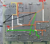
About the hum: if the transformer is near or far the board the hum not vary. now the transformer is 1 meter away from the board. I think that the problem is the layout of my board. I have hum also with open input.
http://img29.imageshack.us/img29/1576/spa1282.jpg
if i separe rectifier and shunt from the riaa board may vary ?
Trace me the rectification GND, shunt GND and Riaa GND with yellow, green, and orange, I want to see if there is a loop.
Don't separate, it isn't field inducing, its better they are tight, good for shunt's output impedance and RF. I will see if there is another way to relate the 3 GNDs. Your caps are close enough for now. I don't know the quality of the output capacitor. Have you evaluated it before? I have only read that it can be a bit treble etched at times besides being very good in general, so the 16.2n maybe balances it by shaving off just a tad more treble than intended with a suggested 16-16.1n.
Don't separate, it isn't field inducing, its better they are tight, good for shunt's output impedance and RF. I will see if there is another way to relate the 3 GNDs. Your caps are close enough for now. I don't know the quality of the output capacitor. Have you evaluated it before? I have only read that it can be a bit treble etched at times besides being very good in general, so the 16.2n maybe balances it by shaving off just a tad more treble than intended with a suggested 16-16.1n.
I compared the output cap with mundorf m-cap PP (white cap) and audyn cap Q4 and i like the sound of K73-16. Open, clean... i must evaluate more, also adding a Ft-2 as bypass. If i got a good working riaa i can spend some extra money for the components. The gnd: i don't see a loop; i did a test, i disconnect in and out gnd from the riaa. In this case don't work, the riaa has a cyclic beat (oscillation?) and the led's flash on-off (riaa's and shunt's leds)
http://img19.imageshack.us/img19/1576/spa1282.jpg
http://img19.imageshack.us/img19/1576/spa1282.jpg
Salas you are a genius as well as being a kind person.
Now the hum is gone, only with the volume at max I hear a slight breath (shhhhhhhhh). And I'm listening through headphones.
When i build the second channel i must connect the star ground of the second channel to the star ground of the first ? star ground for me is where rectification GND, shunt GND and Riaa GND are connected together
No, you will have to make a chassis star earth using screw and nut, where you will connect 2 + 2 black lines from the channels. The black earth symbol I draw in other words represents that point. Also the tonearm grounding post with a wire there. The mains earth you will connect near the IEC socket to the chassis. When you will have stereo and will listen more, and play with your TT set up, VTA etc, tell me more about the tone. Maybe you will need just a couple of Shinkoh.
The FT caps start up a bit coarse but after some play become unified, passing essential info, not hyper detail, go down slide again for a while and then come up again for good. Lets see how your parts assortment comes together.
The FT caps start up a bit coarse but after some play become unified, passing essential info, not hyper detail, go down slide again for a while and then come up again for good. Lets see how your parts assortment comes together.
Hi Salas
Here you have the latest layout for the riaa. Could you please comment on the locations ?
Centre cap is a 100n FT-3 and below is a 47n obbligato gold. In the output there is a 4u7 obbligato gold.
I am doing it p2p but maybe I will build a pcb for later use.
Can I use 680uF caps on C5 and C6 ?
Regards
Ricardo
Attachments
- Home
- Source & Line
- Analogue Source
- Simplistic NJFET RIAA