nicoch46 said:
I will never use digital source
Ops.. only in my car
Maybe you never heard a hot roded CD53
RCruz said:now I would like to bypass the output caps and you suggested 0.047u PIO.... as I do not have any left, I would like to try other caps ... I have some ERO KP 1832 3000pF and some 4700pf styroflex... Can I use these caps or should I buy some 0.047u as per your indications? (My output caps are 4.7uF mundorfs MKP).
Is there a rule for these bypasses ? Should I use 1/10 of the original value or 1/100 ?
Regards
Ricardo
PS Just ordered some 0.1u Teflon CCCP caps just like yours for the Riaa circuit.
Thank you so much for the precious help... The Riaa is starting to sound as big as my superhyper CD53.
Try the ERO. Its a proven bypass. I recommended the K-40 0.047 because I saw you use it, its a good bypass also, and I thought you may had more in hand.
The 0.1 FT3s will make you spin.

For a record to sound as bold as a hyper modded CDP is no mean feat. Consider the signal level domain differences. If you achieved that plus the vinyl's uniquely esoteric and natural presentation, I guess you did more than well already. There is more to come with full use of Shinkoh, output cap tuning and FT3s. Hold on.
Hi Salas
To be honest, only recently I managed to get coherent and detailed sound from the CDP. (I needed to create dedicated psu´s for each chip and the last one on the decoder made the magic)
It took more than one year to mod and finally it outclassed the TT in all aspects but the sweet trebble that vinyl can produce. (I still have to do the coax mod between mech and HF amp to get closer.. )
Now I got a tremendous boost in the TT with your Riaa and it is so promicing that I believe soon the CDP will need a revamp.
Today I changed from 1k82 to 2k21 Rload and I like the added trebble presence but maybe it is too much.... Almost getting there.
Ricardo
PS: Just can´t stop
To be honest, only recently I managed to get coherent and detailed sound from the CDP. (I needed to create dedicated psu´s for each chip and the last one on the decoder made the magic)
It took more than one year to mod and finally it outclassed the TT in all aspects but the sweet trebble that vinyl can produce. (I still have to do the coax mod between mech and HF amp to get closer..
)Now I got a tremendous boost in the TT with your Riaa and it is so promicing that I believe soon the CDP will need a revamp.
Today I changed from 1k82 to 2k21 Rload and I like the added trebble presence but maybe it is too much.... Almost getting there.
Ricardo
PS: Just can´t stop
salas said:Looks OK. But under some threshold, the scope will just show nice lines and it is difficult to evaluate small gains.
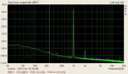
You will need FFT. Here is the FFT of the pictured phono, fed with DL160 nominal 1.6mV 1kHz. The 50Hz peak is the total hum. Good for such a small box with an non shielded transformer inside, and just p2p. That -107dB 100Hz edge might be the ripple residual or just random noise floor grass. Also that 16kHz -105dB peak might be interference from some TV scan frequency.
salas, you've got hum
thanks for the a.r.t.a. link, nice software. I have used it to test the few different versions of the shunt regulator I have built. The spectrum analysis of all of them does not show much difference. In my opinion it is not as easy to see differences as it is on the oscilloscope. Only your version showed a tiny bump on 120 Hz (twice the main frequency of the utility line here) which is in agreement with the bridge rectifier I am using. The buffered version and the very simple darlington version do not show anything at 120 Hz or elsewhere, but that's about the only small difference. All versions are VERY close to the noise floor of the sound card.
For me at least, it is easiest to see any and all funny stuff on the scope, looking at the thickness and shape of the trace at various time/div settings, and at 5mV/div. However, if the differences are difficult to spot on the spectrum analysis curve, then I don't think there will be differences in sound.
Given the performance achieved so far by this family of regulators, I will not explore this issue any longer. Good enough for me. It is my opinion that the opamp buffered version is very, very good, although not as simple as others.
I measured both AC coupled at the output of the regulator, and then passed a 1Khz sine through the phono, and measured at the output of the phono.
The output of the regulator was what I was talking about earlier. The sine passed through the phono shows quite a bit of 60Hz and harmonics, but I don't understand where they're coming from, since the regulator has no trace of such things whatsoever. Could it be ground problems on the phono pcb?
The output of the regulator was what I was talking about earlier. The sine passed through the phono shows quite a bit of 60Hz and harmonics, but I don't understand where they're coming from, since the regulator has no trace of such things whatsoever. Could it be ground problems on the phono pcb?
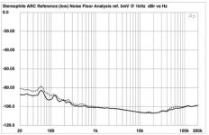
When you measure the phono as a whole there is lots of gain that follows the RIAA shape. See page 38 also. If you have 40dB at 1 kHz for example, you have 60dB gain at 50Hz. So the loop resistance of your GND scheme, the proximity to transformer field, AC cable or other equipment, will induce the mains fundamental, aided much to do so. Even when with battery PSU it will pick up some by surroundings or by not perfect GND by creating little loop with connected system. What you saw in the way I measured it, isn't exponential frequency scaling, but octave scaling, trying to be closer to reality for hiss because its a phono and is going to be fed inverse RIAA. Also the trafo is in the little box. The fundamental sums and diffs with its harmonics. So you got 120+240=360Hz there too for instance. Also some TV is feeding 16kHz scan in your mains too. Still not in a box with PSU and trafo I guess. How far was your trafo and PSU when you measured? My perspective was to keep all that stuff under 60-70dB that would be the max dynamic range of best TT and cart when actually spinning records. More hum will be added by cart ground path and arm cable picking easily when such a low signal travels so long. So my goal was to have JFETS and MOSFETS mainly because they give a nice subjective tone, in the simplest effective form for adequate results. Best lab results for this or that frequency etc make things necessarily more complex, adding high loop feedback op amps etc, for typical gains that will be dwarfed by the reality of a rock dragging on vinyl, sending a tiny signal far away in a non isolated environment. And all hose things hurt the main goal that must be good sound by catering for tech perfection that will be playing second fiddle IMO. I just went over to stereophile phono review measurements to see some and I saw that they avoid the region under 1kHz in most measurements by using linear scaling. I could see only one older full spectrum (yr2000 Audio Research Reference Phono), taken at lowest set gain in exponential scale (noise goes down as frequency goes up following RIAA shape if not inverse fed). Just the noise floor with no signal and the inputs shorted. As you see we must be doing OK with our stuff, don't we?
Attachments
- Home
- Source & Line
- Analogue Source
- Simplistic NJFET RIAA