guglielmope said:but I where I can find info about matching fets or buy matched ones?
Thanks a lot for your help and interest
Grazie
Guglielmo
Idss matching
salas said:
The standard 28V LED shunt that Rcruz made, he reported it dead silent. That is all I can personally know.
The shunt is really silent and ultra fast.
Just did the 330pF mod and now everything is getting into the right place.

Now I will play with the cart loading.
Amazing !
Ricardo
The only difference I noticed between the two versions of the regulator is that the power mosfets of the non-buffered one get very hot, even with a significant heat sink. The buffered version you mentioned above has cold mosfets; the darlington gets a little warm (I measured a 27 mA collector-emitor current). On the oscilloscope both show a nice regulated trace, and sound wise I could not notice any difference. The reason I mentioned it to salas was partly theoretical, furthermore, I like tweaking everything, no offense intended.
Rather odd to have cold Mosfets if the CCS is running same current in both versions. I would expect the shunt Mosfet to be somewhat colder since the driver and the idss buffer would consume about 37mA above load consumption VS the standard one, lightening its constant burden. But I don't see how the CCS Mosfet running at same current and same Vin - Vout can show such a thermal difference. Plus if they share the same heatshink they would eventually come to about the same centigrade.
Hi Guglielmoguglielmope said:Hello Riccardo,
There isn' t any330p on the schematic, where I can find this update?
Do you had any problem with pcb?they was ok?
The original 46dB schematic indicates 16nF for C3 on the riaa circuit.
As I was using 15.72nF, I added 330pF so I got 16.05nF.
The result is very noticeable... I lost the frontal presentation of sax and trumpet, voices became less boxy and piano has a natural presentation. the 330p silver micas are burning nicely and the trebble is regaining it´s fluidity.
The pcb is very good indeed... everything worked at the first time !
Now I will replace some resistors and work on a propper case with good connectors.
Ricardo
salas said:Rather odd to have cold Mosfets if the CCS is running same current in both versions. I would expect the shunt Mosfet to be somewhat colder since the driver and the idss buffer would consume about 37mA above load consumption VS the standard one, lightening its constant burden. But I don't see how the CCS Mosfet running at same current and same Vin - Vout can show such a thermal difference. Plus if they share the same heatshink they would eventually come to about the same centigrade.
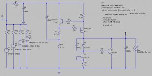
Yes, it puzzle me too. I did some digging yesterday; my suspicion was that the bjt did all the work in the second stage of regulation, the shunt stage, and thus the second mosfet did no more work. I measured the current through the first mosfet, at about 97 mA, and that seems sane. The current through the second mosfet was less than 1 mA. Logically, next I removed the entire buffer+second mosfet. Right now I am running the attached configuration with great results I might say. The darlington can be replaced with other medium power transistor, I use it because it's what I had around in the junk box. I can say this with certainty, because I did compare yesterday with a lm317, and a lm338t. The shunt regulator is much better, both versions yours, salas, and the one that I slightly modified.
")
salas, so have you formed an opinion about the ruskie ft-3s?
Attachments
Well,
Thorsten used the "japan way" of riaa in his ECC83/88 combo.
The C values are independent, not fixed in the classic 1 to ~3 way.
The formula for this riaa approach isn´t in the Lipshitz papers. I´m sorry, I never find the real formula.
Thorsten told me, that he too doesn´t know the formula, but he constructed his riaa by simulating.
Can anybody share the formulas for this kind of approach?
Then we are independent off the Lipshitz 1 to ~3 c-values.
Carsten
ikoflexer said:
The shunt regulator is much better, both versions yours, salas, and the one that I slightly modified.
salas, so have you formed an opinion about the ruskie ft-3s?
In what way is better with the shunt BJT?
Not yet, I will get them FT3s in very soon.
carawu said:
Can anybody share the formulas for this kind of approach?
Then we are independent off the Lipshitz 1 to ~3 c-values.
Carsten
I simulated with inverse RIAA and then measured against mathematically generated RIAA curve. I used no formulas.
Regards
ikoflexer said:However, I would like say that I am just exploring some of these variations, and to recommend to everyone to run the salas shunt regulator.


I would think that using a power Darlington instead of a small BJT and Mosfet, gains much in HFE and you don't have to drive a capacitive gate. The only thing practical is that it has to prove itself at 200mA and reliability against time and oscillation tendencies. If it proves good long term behavior, why not recommend it over the BJT+Mosfet? Its one component less so it is a ''Simpler Simplistic''.
salas said:
In what way is better with the shunt BJT?
Not yet, I will get them FT3s in very soon.
I meant both versions are better than the lm317 and lm338t. Big difference there. I cannot say the bjt is better than anything else.
salas said:I understood that, that is why I did the shunts so to upgrade from battery and LMs. I ask because you said ''with great results''. No differences on the subjective front with the power Darlington?
My ears cannot spot a difference. I'd trust other people's ears over mine. But it's such an easy variation that I'm surprised you're not trying it. Then again, if yours works as up to your expectations there is no reason to waste time with others. I think I've said it before, as much as I am interested in results, I also enjoy the exploration aspect.
Off course I will try it given the first chance. I wrote in few posts above that everything making it simpler and still working at least equally for sound without long term reliability problems is welcome. I sidestepped Darlingtons, was in my head right from the start, because I was afraid of oscillation possibilities for the average DIY attempt. I have the measuring and debugging capability to stabilize, I just wanted it easy for all. But the design proved robust against truly high HFE in your hands. So I will try. Good work.
Hi folks
Just been reading through this thread and am a litle confused as to the best schemtic to use with my Denon 103-R version? Also which PSU and do I need a shunt? Sorry, I know these are probably simple questions to many here.
It'll be used with a solid-state (KingRex Pre) pre-amp for the moment, running into a www.41hz.com Amp6 Basic, or also a Dynaco ST70 with VTA driver board depending on my musical mood
Any help would be greatly appreciated.
Many thanks,
- John
- Home
- Source & Line
- Analogue Source
- Simplistic NJFET RIAA