
We'll see if it works in reality  but it sure looks promising.
The other thing I was playing with, but didn't get far, was meant to replace the 20 something V zener with some other reference. The higher voltage zeners are, apparently, more noisy than the lower voltage ones. Something based on the lm369 or some other low noise buried zener reference. We'd probably end up with a super nice solution. Not that we need anything better than what we've got already, but hey, what the hey.
but it sure looks promising.The other thing I was playing with, but didn't get far, was meant to replace the 20 something V zener with some other reference. The higher voltage zeners are, apparently, more noisy than the lower voltage ones. Something based on the lm369 or some other low noise buried zener reference. We'd probably end up with a super nice solution. Not that we need anything better than what we've got already, but hey, what the hey.
 Devil will find work for idle hands to do
 ikoflexer said:We'll see if it works in reality
The other thing I was playing with, but didn't get far, was meant to replace the 20 something V zener with some other reference. The higher voltage zeners are, apparently, more noisy than the lower voltage ones. Something based on the lm369 or some other low noise buried zener reference. We'd probably end up with a super nice solution. Not that we need anything better than what we've got already, but hey, what the hey.
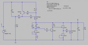
Remember to match J2, J3 when prototyping. Also the Zener is well bypassed and CCSed so its self noise is pushed down in practice. Don't make it more elaborate there IMO. What we did by now is to idealize the npn driver bjt which bares logic.
By the time I saw your reply I already built it. I didn't pay attention this time to matching j2 j3, just wanted to put something together quickly.
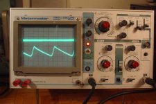
Attached is a trace. The bottom trace is the input to the regulator, a 100 mV p-p voltage, the top one is the regulator output, shown on 5mV/div on the scope, the tightest so far I got from any version regulator I tried. Don't know how it sounds.
I've replaced Q1 with a 2n6387 (darlington ) because q1 was getting hot and I didn't want to search around too much.
I'm sure this circuit can be done even better than my aerial construction and probably the results will be even better.
We might have hit a small jackpot here. If only I had one of those cards to run some real psrr measurements on it... would be neat. I think I might get this, what do you think:
http://cgi.ebay.ca/ws/eBayISAPI.dll?ViewItem&item=290293080263&fromMakeTrack=true&ssPageName=VIP:Watchlink:middle:ca
Attached is a trace. The bottom trace is the input to the regulator, a 100 mV p-p voltage, the top one is the regulator output, shown on 5mV/div on the scope, the tightest so far I got from any version regulator I tried. Don't know how it sounds.
I've replaced Q1 with a 2n6387 (darlington
) because q1 was getting hot and I didn't want to search around too much.I'm sure this circuit can be done even better than my aerial construction and probably the results will be even better.
We might have hit a small jackpot here. If only I had one of those cards to run some real psrr measurements on it... would be neat. I think I might get this, what do you think:
http://cgi.ebay.ca/ws/eBayISAPI.dll?ViewItem&item=290293080263&fromMakeTrack=true&ssPageName=VIP:Watchlink:middle:ca
The card is good to get. To tell you the truth I haven't measured any 100Hz ripple spike on FFT with simpler shunt versions on the phono output as well, always buried in the grass, but the buffer to the V MOSFET can not hurt. Where is your measuring point? At dummy load or on phono's B+ including cable? How much current on load if with dummy? The key is the sound. To really hear something better. Try with headphones, you may discern and tell us. Only let it run enough before critical listening (2 days powering), I know that it smooths out in a day or two when from new, by experience. To preserve lower impedance gains, the output cap must be very low ESR (bypass with 0.1uF film), and the twisted cabling to phono B+ point and GND point, speaker grade thick. Congratulations for your results! Refreshing.
Hi Salas
Just finished measuring the jfets.
I arranged them in lots with values from 10.9 mA to 8.4 mA.
I also have smaller values like 6.4 6.5 6.7 6.8 (without pairs)
What avlues should I use for eac place in the RIAA ?
(Also matched the BC550C using the DMM hFE)
Ricardo
Just finished measuring the jfets.
I arranged them in lots with values from 10.9 mA to 8.4 mA.
I also have smaller values like 6.4 6.5 6.7 6.8 (without pairs)
What avlues should I use for eac place in the RIAA ?
(Also matched the BC550C using the DMM hFE)
Ricardo
Attachments
a waste of time.RCruz said:matched the BC550C using the DMM hFE
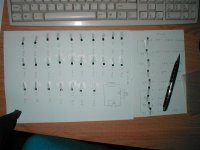
You have pre-selected your To92 devices ready to find some matches.
RCruz said:Hi Salas
What avlues should I use for eac place in the RIAA ?
(Also matched the BC550C using the DMM hFE)
Ricardo
Try to keep them 8.5 to 9mA range and matched near 0.1mA per pair and position. You can use the 10mA stuff for the Zener CCS and buffer.
It is not that critical for the BJTs since the lower part of the cascode mainly defines its output impedance, but not entirely futile, bcs matched hfe means matched for noise between channels as well.
salas said:
Try to keep them 8.5 to 9mA range and matched near 0.1mA per pair and position. You can use the 10mA stuff for the Zener CCS and buffer.
It is not that critical for the BJTs since the lower part of the cascode mainly defines its output impedance, but not entirely futile, bcs matched hfe means matched for noise between channels as well.
Thank you Salas... You are unreal!!!

I still have 40 jfets to match... should I look for a lower Idss ?
Please take a look at my data. I did a pivot table chart so we can know how many matches we have by value.
In the data table, I converted the mV readings into mA.
Ricardo
Attachments
salas said:The card is good to get. To tell you the truth I haven't measured any 100Hz ripple spike on FFT with simpler shunt versions on the phono output as well, always buried in the grass, but the buffer to the V MOSFET can not hurt. Where is your measuring point? At dummy load or on phono's B+ including cable? How much current on load if with dummy? The key is the sound. To really hear something better. Try with headphones, you may discern and tell us. Only let it run enough before critical listening (2 days powering), I know that it smooths out in a day or two when from new, by experience. To preserve lower impedance gains, the output cap must be very low ESR (bypass with 0.1uF film), and the twisted cabling to phono B+ point and GND point, speaker grade thick. Congratulations for your results! Refreshing.
Meaured at the dummy load. I didn't check the current at the load. I've listened to it last night on the headphones. Subjectively only, I can say that it sounds "alive", very fresh. But this was a quickly put together prototype, without care on the layout and parts; probably can be improve with some care.
A film cap with low ESR? Be careful there, I haven't yet measured a film cap with low ESR. I just didn't put any film caps on the output.
And yes, it's nice to see the regulator so stable.
RCruz said:In the data table, I converted the mV readings into mA.
Ricardo
Can't read it. Is it a txt file?
it's an XLS file and opens in Excel.salas said:Can't read it. Is it a txt file?
salas said:I mean a polypropylene 0.1uF to 0.22uF in parallel with the 470uF output cap so to kill the lytic's rising impedance due to its ESR.
I hear you sir. Any pointers to particular makes of polyprop caps with low ESR? I have quite a bunch of them of different makes, and not one has low ESR but I do have already have some electrolytic ones with low ESR.
I forgot to mention something else different in the buffered regulator. The power mosfets are COLD. They run at much lower quiescent current. The simulation does not show especially much current going through the darlington, yet it gets warmest of them all. I am not inclined to change it again for a highest current through the mosfets, it if works already so well.
- Home
- Source & Line
- Analogue Source
- Simplistic NJFET RIAA