Maybe something wrong with the CCS, shows 3.4-3.6V VGS normally. And if it works, a CCS cuts ripple by definition down to a rudimentary amplitude. You can also try a LM317 CCS configured to feed your point to point test, by passing your now CCS. Just to see if it cuts ripple so to know in what part of the circuit the bug is. Also there is at least one company (MICRO ELECTRONICS) that has BC550 as CEB when normal is CBE.
Nice one!
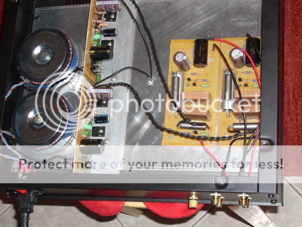
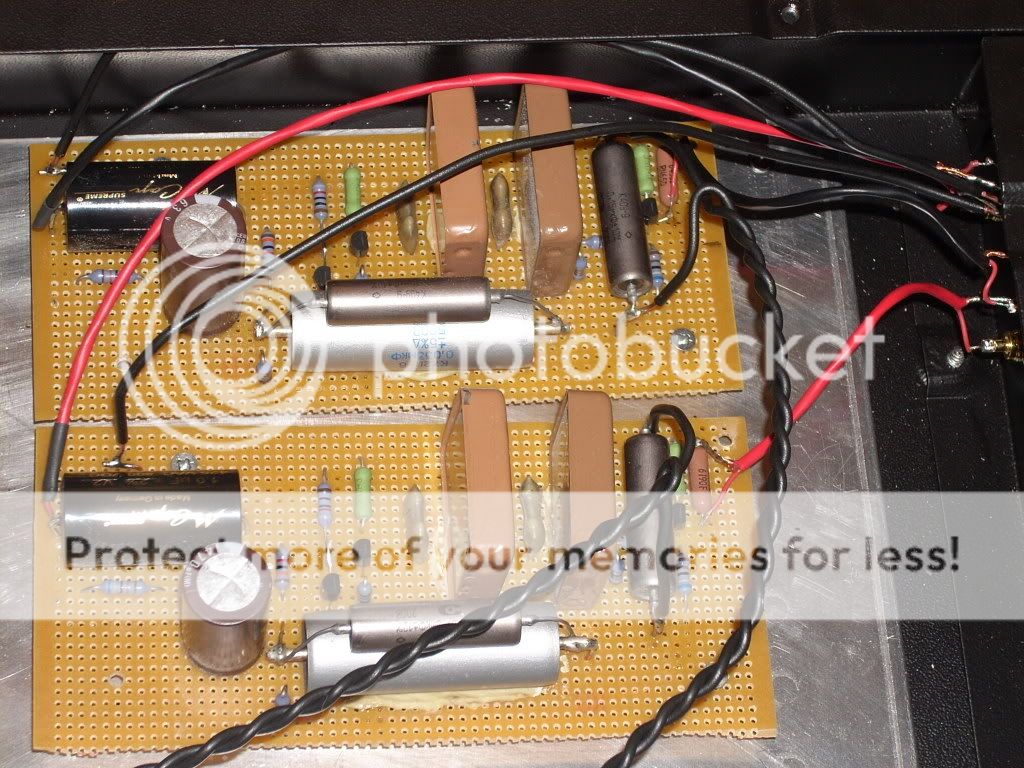
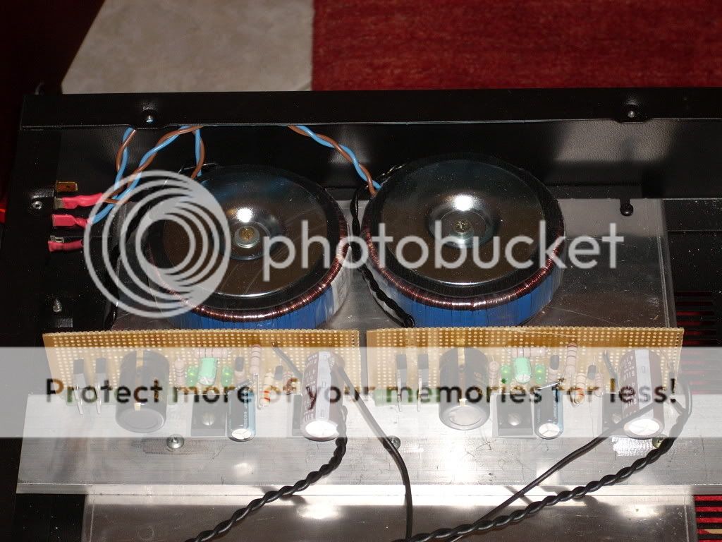
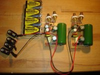
Fresh double mono shunt PSUs, point to point & Soviet caps galore.
Zero hum or buzz, dead black background. Burning in phase, will let you know more of any subjective gains at this level of construction soon. The good work is done by Michael here in Athens.

Fresh double mono shunt PSUs, point to point & Soviet caps galore.
Zero hum or buzz, dead black background. Burning in phase, will let you know more of any subjective gains at this level of construction soon. The good work is done by Michael here in Athens.
Attachments
Hi Salas!
Today i have build post 110 ver.
4x9v recharg. is psu.
Sound is impressive for such low budget.
My friends at www.hififorum.nu advice me not to build the shunt psu.
They say zeners buzz etc.
Today i have build post 110 ver.
4x9v recharg. is psu.
Sound is impressive for such low budget.
My friends at www.hififorum.nu advice me not to build the shunt psu.
They say zeners buzz etc.
Attachments
Re: Nice one!
Quite cool indeed
It seems the shunt does not need a lot of capacitance in the input... I was planning a 10.000u but now I doubt if it is benefitial...
Also I am using several 1/2w resistors... (Only R1 will be 2W).. is it dangerous ?
Ricardo
salas said:Fresh double mono shunt PSUs, point to point & Soviet caps galore.
Zero hum or buzz, dead black background. Burning in phase, will let you know more of any subjective gains at this level of construction soon. The good work is done by Michael here in Athens.
Quite cool indeed
It seems the shunt does not need a lot of capacitance in the input... I was planning a 10.000u but now I doubt if it is benefitial...
Also I am using several 1/2w resistors... (Only R1 will be 2W).. is it dangerous ?
Ricardo
hoktuna said:Hi Salas!
Today i have build post 110 ver.
4x9v recharg. is psu.
Sound is impressive for such low budget.
My friends at www.hififorum.nu advice me not to build the shunt psu.
They say zeners buzz etc.
Thanks for your nice comments. As for advices from people that had never made the shunt...think simple. Would someone ever decide to build a double mono with 2X100W TXs, Mlytics, HFA diodes, Silmc 2 output, copiously in P2P, after having used large batteries (PanaFC bypassed), LM317, vbe & LED shunt, just to enjoy a buzz?????
Fellas, get a grip!
''Mpravo file mou - einai omorfia auto to kukloma, sugxaristiria !
I tried a quick mock-up of your shunt (point-to-point) and it works like a charm. Input was from wall-wart with very high ripple (200 mV peak) and instead of your discrete CCS I used LM317 as CCS set for 85 mA. I loaded the shunt with 10mA to 60 mA and there was no sign of ripple or oscillation on my scope (10mV/DIV sensitivity). I used the parts that I had at hand and it worked nicely from the start.
Test with JFET BOZ (circuit with no PSR at all) was successful - no hum, no hiss, completely black background, sounds lovely, noticeably better than 7815.
Good job, thank you ! ''
Link for above comment
''Salas,
Tried the shunt-reg with CCS and cap bypass-loved it! Really made the RIAA sing. I added a .1uf pp to the diode bypass cap and reduced the output bypass to 100uf and .1uf pp. I think it works better with the 100uf/.1uf pp on the output.
Just for grins I hooked it up to my all tube RIAA (runs on 24V battery). WOW what a difference. If it wasn't for the fact the tubes are to noisy for my Audioquest LO MC (.23 mV), I would just use it. If I still had my Blue Point HO MC I would have never tried this RIAA. Anyone who is using this HAS TO use the shunt-reg.''
Link for above comment
''I got to listen to the HV shunt late last night, background is "blacker", overall sound is faster without harshness, voicing and timber has improved. I'm running one per channel in the line stage. Needless to say the Lambda No. 28 is now up for sale. Didn't think anything would beat the LCLCLC filter and the No. 28. I have tried the Allen Wright SuperReg and the Janus, both have ICs. While both are very good, I prefer the KISS approach and it does sound better. Anyone who is looking for a GREAT simple shunt regular, this IS the way to go. Again a big "thanks" to Salas.
Link for above comment
Please guys, enough is enough, with shunt this shunt that. Anybody who can't tackle a simple reg, revert to batteries. Seriously.
nicoch46 said:Well done Salas!!
tx and diode ?
Thanx Manu. Look at the above post, I answered there for TX and diodes. Also full Shinkoh, 2 Dale and 2 Kiwame on phono, Soviet Mica, K40Y-9//K72p-6, Mundorf Supreme (no oil). Mogami coax, OFC single strand copper for gnd.
Re: Re: Nice one!
No danger with your resistors. As for bigger filter caps, they can't do harm at least. Do a test with smaller ones in the future when you will be all set and familiar enough, so it see if there is any subjective benefit with one or another. And let us know off course.
RCruz said:
Quite cool indeed
It seems the shunt does not need a lot of capacitance in the input... I was planning a 10.000u but now I doubt if it is benefitial...
Also I am using several 1/2w resistors... (Only R1 will be 2W).. is it dangerous ?
Ricardo
No danger with your resistors. As for bigger filter caps, they can't do harm at least. Do a test with smaller ones in the future when you will be all set and familiar enough, so it see if there is any subjective benefit with one or another. And let us know off course.
ikoflexer said:Still with ripple. What's puzzling is that it holds the output voltage constant, so it does regulate. There is just that ripple.
What is your DC in? Maybe you are low on Vin-Vout margin? I know, very basic. But we did not mention it. If the margin is tight and comparable to VGS, ripple can creep in.
Shunt is ready... working as planned... +28V
How can I test it before implementation ?
Can I feed it into a line input in a preamp (After a coupling cap of course) ?
Ricardo
PS The heatsinks must be isolated from each other ? I noticed one ugly spark when I pressed them together (to test for heat), so i placed a plastic sheet between them..
How can I test it before implementation ?
Can I feed it into a line input in a preamp (After a coupling cap of course) ?
Ricardo
PS The heatsinks must be isolated from each other ? I noticed one ugly spark when I pressed them together (to test for heat), so i placed a plastic sheet between them..
Attachments
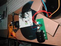
If the Mosfets are not isolated with mica or silicone pads, they must not touch together. You get better heat transfer without pads, and better use some silicone grease for the surfaces to mate better. Good transfer is half the job. If they are not going to touch the chassis, or together, use them like that, bcs you don't have that big sinks. Huh? They survived touching together? Tough shuntie! No don't feed any preamp's in. Do you have a circuit that uses +28V or about to power? Else wait for your phono. How much DC input it gets? What is the VGS of Q1? What is the drop on R1?
No don't feed any preamp's in. Do you have a circuit that uses +28V or about to power? Else wait for your phono. How much DC input it gets? What is the VGS of Q1? What is the drop on R1?Hi Salas
Just a fast reply during lunch time....
The Shunt survived the spark... now the heatsinks are isolated but too small... they get really hot.
With a 560ohm load in the output I get Vout = 27.8v
Vin = 43v
R1 Vdrop 2.3v
How do I measure VGS of Q1 ?
Ricardo
Note: Output cap is 220uF instead of 470.... waiting for BG
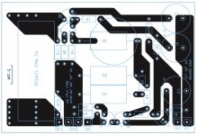
pcb layout revisited...
Here is my revised RIAA board layout. I wanted to see if I could lay it out with separate power ground and approach a more star ground. I really have fun doing these!
The circuit 'wraps' around a central ground pad, so input and out are close; to butt up against the back of a cabinet.
I also tried to give even more room for the signal caps, particularly the Russian teflons. I decided they would fit best standing tall (mine are 53 x 26 mm). Not the best way but it fits and board is still only about 11 x 7 cm, nice and compact. I left the input cap out as I'm doing this for MC.
I'm no pro but figured I keep signal traces short and as far away from each other. Look any good?
Listening update- still making little tweaks. Playing with load resistors and made some cables out of mil-spec silver plate coax (which did help hum a fair bit).
I accidentally put in some RLoads of 82k (thought they were 8.2k). Better- fleshed out the mid-bass and smoother highs. Less 'shouty' ?!?
-Kent
Attachments
RCruz said:Hi Salas
Just a fast reply during lunch time....
The Shunt survived the spark... now the heatsinks are isolated but too small... they get really hot.
With a 560ohm load in the output I get Vout = 27.8v
Vin = 43v
R1 Vdrop 2.3v
How do I measure VGS of Q1 ?
Ricardo
Note: Output cap is 220uF instead of 470.... waiting for BG
Hey Ricardo, it survived a short to ground if you noticed!
Your heatsinks are really small. The way the board is configured with the Mosfets near to each other there are two ways to beat heat. One is a common 1c/W sink and insulation pads, the other is to run about 100mA only, as Kent did and leave it as it is. For the moment, calculate your new R1 for 100mA. If it is a 10R now you got 230mA, if 15R you got 150mA. Your sinks are 2-3W jobs that they usually bolt LM317T or BD140 on. Those Mosfets are really tough survivors. Your Vin-Vout is great and your Tx chunky as I see from the photo. Your 560R dummy load gets about as much as your phono channels will get both, so the heat you experience is gonna be the same in true life. Reduce for long life.- Home
- Source & Line
- Analogue Source
- Simplistic NJFET RIAA