nicoch46 said:
>disconnect the main heart , if is this put two diode reversed with ntc like Pass
Sorry, I don't understand this suggestion. Could you please explain?
salas said:
Is it something that came up after the initial tests? A buzzz indicates 100Hz. See the psu output on the scope. If it still works OK with a clean output, its a ground loop, or a transformer field. Batteries are essentially floating devices.
It was probably there, but I usually don't pay attention to such things in the beginning. The scope shows a spike about 10mV/div high on the PSU output, but I didn't check the frequency. The transformer was quite far from the regulator and preamp, far enough for it's field not to affect anything, I think. I suspect the psu as the main culprit, or a ground loop/problem.
salas said:This PSU does not pass 100Hz ripple for sure by design. Many have been built and work for months now. There must be some error somewhere if it does so.
Do you mean the regulator?
ikoflexer said:or a ground loop/problem.
If you will not find 100Hz on the PSU's output (which may be fortunate if there is just a small error to fix), case of having some ground loop is a bad situation to solve some times. I hope not. What about your TT ground wire? Is it grounded OK?
ikoflexer said:
Do you mean the regulator?
Yes. I mean PSU as a whole, including the regulator. You refer to just the raw PSU before the reg?
ikoflexer said:
Sorry, I don't understand this suggestion. Could you please explain?
He probably means to float the mains earth and use a couple of mutually reversed parallel diodes that will open up in case of emergency and restore earthing. If I got this right, Nicoch will present me a master's in Nicochian linguistics.

Attachments
Yes, the TT ground cable was properly connected. I still tried different connections for it, but no change.
I was referring to the trafo+bridge+CLC filter as the psu, just to keep it separated logically from the regulator. Surely it's something stupid I've done, I'll check things again tonight.
What I don't understand from what you said salas, is, do you mean that even if there is ripple going into the regulator, the regulator should flatten it out? It certainly behaves so in simulation...
ikoflexer said:
Sorry, I don't understand this suggestion. Could you please explain?
disconnect the main earth
 sorry I don't speak english
 ikoflexer said:What I don't understand from what you said salas, is, do you mean that even if there is ripple going into the regulator, the regulator should flatten it out? It certainly behaves so in simulation...
Yes it will cut out any input ripple with its negative comfortably above the VGS threshold of Q1. Imagine the CCS as an extremely large choke that isn't storing energy. See here post#157, for a practical test report.


RCruz said:My trafo for the shunt just arrived 80VA 2 X 0-15V Nuvotem encapsulated....I believe I will have enough headroom
Nice. Did you populate the board yet?
ikoflexer said:You guys are hilarious
In a good way, of course.
Why not...it is such a perfect day, listening to TTs relaxes us.
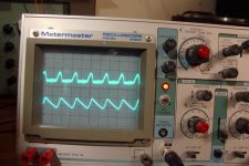
This picture explains a lot. The upper trace is what comes out of the regulator, the lower trace is taken right after the diode bridge. The two traces are scaled differently, but the main idea is that their frequency coincides. The regulator output was not connected to anything. It looks like my implementation of the regulator somehow does not flatten the ripple. I just noticed that my bjt is a BC550B, not a BC550C. Would the different hfe (330 vs 600) make such a difference? I'll look around here see if I got something like a BC550C.
- Home
- Source & Line
- Analogue Source
- Simplistic NJFET RIAA